
1. Introduction
This manual provides essential information for the safe and effective use of the GODIYMODULES WM-045-001 Automatic Step Up Step Down DC-DC Converter. This module is a non-isolated synchronous rectification constant voltage and constant current buck-boost power supply module designed for various applications requiring stable voltage output from a fluctuating input.
Key features include:
- Automatic step-up and step-down voltage regulation.
- Input voltage range: DC 5V-30V.
- Output voltage range: DC 1.25V-30V.
- Integrated protection functions: short circuit, over current, and over temperature.
- Constant voltage and constant current adjustable output.
2. Safety Information
Please read and understand all safety instructions before operating the module. Failure to follow these instructions may result in electric shock, fire, or damage to the product or connected devices.
- Electrical Safety: Always ensure power is disconnected before making any connections or adjustments.
- Polarity: Observe correct input and output polarity. Incorrect connections can damage the module and connected equipment.
- Heat Dissipation: The module generates heat during operation. Ensure adequate ventilation and consider auxiliary heat dissipation, especially at higher loads.
- Short Circuits: Avoid short circuits at the input and output terminals. While the module has short-circuit protection, prolonged short circuits can cause damage.
- Isolation: This is a non-isolated module. Input negative and output negative terminals should be kept independent and not connected in common to maintain current detection and protection functions.
- Environment: Do not expose the module to moisture, dust, or extreme temperatures.
3. Product Overview
The WM-045-001 module is designed for robust performance in various voltage stabilization applications. It features a large heat sink for efficient thermal management and uses high-power components to ensure stability and reduce ripple.
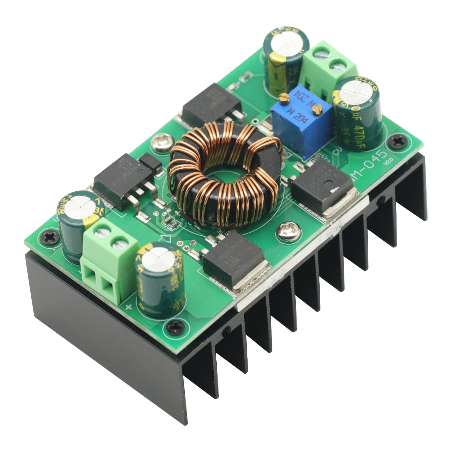
Figure 3.1: Top view of the WM-045-001 module, showing the inductor, capacitors, and heatsink.

Figure 3.2: Angled view of the module, illustrating the input and output screw terminals, and the voltage and current adjustment potentiometers.

Figure 3.3: Annotated diagram indicating input voltage (DC 5V-30V), output voltage (DC 1.25V-30V), power indicator, and the locations for current and voltage regulation.
4. Setup and Connection
Follow these steps to set up and connect your DC-DC converter module:
- Identify Terminals: Locate the 'POWER IN' terminals for input and the 'OUTPUT' terminals for output. Ensure you identify the positive (+) and negative (-) terminals correctly.
- Input Connection: Connect your DC power source (5V-30V) to the 'POWER IN' terminals. Ensure the polarity is correct.
- Output Connection: Connect your load to the 'OUTPUT' terminals. Ensure the polarity is correct.
- Initial Voltage Adjustment: Before applying power to your load, it is crucial to adjust the output voltage. Connect a voltmeter to the output terminals. Power on the module (without load) and use a small screwdriver to turn the voltage regulation potentiometer (labeled 'V ADJ' or similar, typically the blue potentiometer with 'W 204' marking) until the desired output voltage is achieved. Note that these are precision potentiometers and may require multiple turns to see a change.
- Current Limit Adjustment (Optional): If you need to set a current limit, connect an ammeter in series with the output and a suitable load. Adjust the current regulation potentiometer (labeled 'I ADJ' or similar) to set the desired maximum output current.
- Final Connection: Once voltage and current are set, connect your load.
Important Note: Input and output are strictly prohibited to be reversed. The output contains an anti-reverse function to prevent charging back, but incorrect input polarity can damage the module. Input negative and output negative need to be independent of each other and should not be connected in common, as this may disable current detection and protection functions.
5. Operating Instructions
Once the module is set up, it will automatically regulate the output voltage based on the input voltage and the set parameters. The module can step up or step down the voltage as needed within its operational range.
- Voltage Stabilization: The module is ideal for applications where the input voltage fluctuates, such as with solar panels, and a stable output voltage is required for equipment or battery charging.
- Monitoring: Periodically monitor the module's temperature, especially during continuous operation at higher loads. If excessive heat is observed, reduce the load or improve ventilation.
- Parallel Operation: For applications requiring higher output current than the module's maximum (e.g., above 5A continuously), it is recommended to use two modules in parallel to distribute the load and manage heat more effectively.
6. Maintenance
The WM-045-001 module is designed for reliable operation with minimal maintenance. However, adhering to the following guidelines can prolong its lifespan:
- Keep Clean: Ensure the module is free from dust and debris, which can impede heat dissipation.
- Inspect Connections: Periodically check all electrical connections to ensure they are secure and free from corrosion.
- Environmental Control: Operate the module within its specified environmental conditions (temperature, humidity) to prevent premature component failure.
7. Troubleshooting
If you encounter issues with your module, consider the following troubleshooting steps:
- No Output Voltage:
- Check input power supply.
- Verify input polarity.
- Ensure the voltage adjustment potentiometer has been turned sufficiently. Some units may ship with a default setting that needs adjustment.
- Module Gets Hot:
- This is normal under load, but excessive heat indicates an issue.
- Reduce the output current. The module is rated for a maximum of 8A (10A peak), but continuous operation at 5A is recommended to manage heat.
- Improve ventilation around the module or consider auxiliary cooling (e.g., a fan).
- Ensure the load is not exceeding the module's power rating (150W continuous, 300W peak).
- Output Voltage Unstable:
- Check for loose connections.
- Ensure the input power source is stable.
- Verify that the input negative and output negative are not connected in common.
- No Current Limit Function:
- Ensure the input negative and output negative are not connected in common, as this can disable current detection.
- Verify the current adjustment potentiometer is correctly set.
8. Specifications
| Parameter | Value |
|---|---|
| Model | WM-045-001 |
| Input Voltage | DC 5V - 30V |
| Output Voltage | DC 1.25V - 30V |
| Output Power | 150W (continuous), 300W (maximum) |
| Output Current | Recommended 5A, Maximum 8A (Peak 10A) |
| Working Frequency | 150KHz |
| Conversion Efficiency | Not less than 80% |
| Protection Functions | Short circuit, Over current, Over temperature |
| Dimensions (L x W x H) | Approx. 76mm x 45mm x 43.3mm |
| Weight | Approx. 0.1 Kilograms |
| Mounting Type | PCB Mount |
9. Warranty and Support
For warranty information and technical support, please refer to the documentation provided at the time of purchase or contact your seller directly. Keep your purchase receipt as proof of purchase.


