XJM60D-21400
XJM60D-21400 Controller of Data Collector User Manual
Model: XJM60D-21400 | Brand: Generic
1. Product Overview
The XJM60D-21400 is a versatile data collector controller designed for industrial applications. It features a robust self-extinguishing ABS housing, DIN rail mounting, and a clear 2-row, 4-digit multicolor LED display. This controller supports a wide range of analogue and digital inputs, making it suitable for various sensing and control tasks. Its compact design and comprehensive I/O capabilities provide a reliable solution for data acquisition and process control.
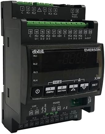
Figure 1: Front view of the XJM60D-21400 Controller, showing the display, control buttons, and various terminal blocks for connections.
2. Specifications
| Feature | Description |
|---|---|
| Housing | Self-extinguishing ABS Case, 4 DIN, 70x135mm; depth 60mm |
| Mounting | DIN rail |
| IP Protection | IP20 |
| Terminals | Pluggable terminal blocks, wirings ≤2.5mm² |
| Power Supply | 24Vac/dc ±10% |
| Power Absorption | 10 VA max |
| Display | 2 rows, 4 digits, multicolor LED |
| Analogue Inputs | Up to 6 (PT1000, PTC, NTC, 4-20mA or 0-10V) |
| Digital Inputs | Up to 6 not insulated and 6 insulated |
| Pulse Counters | Maximum input signal frequency 10 Hz |
| Analogue Output | 0-10Vdc or 4-20mA |
| Digital Outputs | RL1, RL2, RL3, RL4: relay SPST 5A; 250Vac |
| Data Storing | Internal non-volatile memory (EEPROM) |
| Operating Temperature | 0 to 55°C |
| Storage Temperature | -25 to 70°C |
| Relative Humidity | 20 to 85% (not condensing) |
| Item Weight | 1.21 pounds (0.55 Kilograms) |
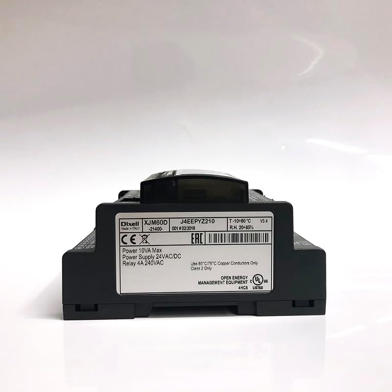
Figure 2: Rear view of the XJM60D-21400 Controller, displaying the product label with model number, power specifications, and certifications.
3. Setup
3.1 Unpacking and Inspection
- Carefully remove the controller from its packaging.
- Inspect the device for any visible damage. If damaged, do not proceed with installation and contact your supplier.
- Verify that all included components (buckle, sensor, packaging box) are present as listed.
3.2 Mounting
The XJM60D-21400 is designed for DIN rail mounting. Ensure the DIN rail is securely installed in a suitable enclosure that provides adequate ventilation and protection from environmental factors.
- Align the controller's DIN rail clip with the DIN rail.
- Press firmly until the controller snaps securely into place.
- Ensure the device is stable and does not wobble.
3.3 Wiring Connections
All connections are made via pluggable terminal blocks. Ensure power is disconnected before making any wiring connections. Use wiring with a cross-section of up to 2.5mm².

Figure 3: Top view of the XJM60D-21400 Controller, illustrating the various pluggable terminal blocks for power, digital, and analog inputs/outputs.
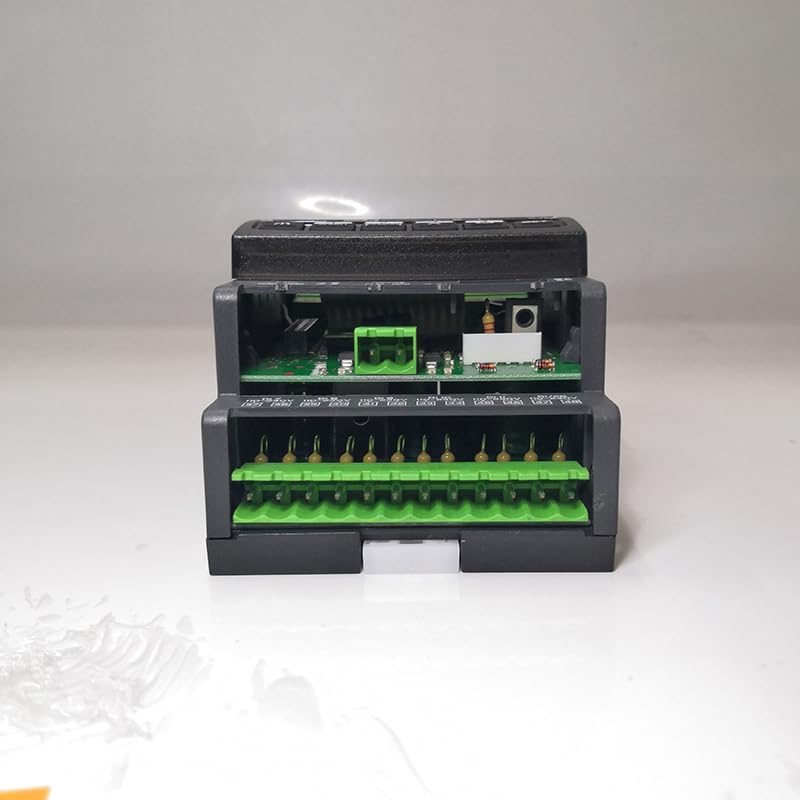
Figure 4: Bottom view of the XJM60D-21400 Controller, showing additional terminal blocks for LAN, RS485, and other connections.
- Power Supply: Connect 24Vac/dc ±10% to the designated power terminals.
- Analogue Inputs: Connect PT1000, PTC, NTC sensors, or 4-20mA/0-10V signals to the respective analogue input terminals.
- Digital Inputs: Connect digital signals to the insulated or non-insulated digital input terminals as required.
- Analogue Output: Connect devices requiring 0-10Vdc or 4-20mA signals to the analogue output terminals.
- Digital Outputs (Relays): Connect loads to the SPST 5A; 250Vac relay terminals (RL1, RL2, RL3, RL4).
- Communication: Utilize LAN and RS485 terminals for network integration as per system requirements.
Ensure all connections are secure and correctly polarized to prevent damage to the device or connected equipment.
4. Operating Instructions
4.1 Powering On
Once all wiring is complete and verified, apply power to the controller. The multicolor LED display should illuminate, indicating the device is operational.
4.2 Display and Navigation
The 2-row, 4-digit multicolor LED display provides real-time data and access to configuration menus. Use the control buttons (e.g., Menu, Section, Up, Down, Set) on the front panel to navigate through parameters and settings.
- Menu Button: Enters or exits the main menu.
- Section Button: Navigates between different sections or parameters within a menu.
- Up/Down Buttons: Adjusts values or scrolls through options.
- Set Button: Confirms selections or saves changes.
4.3 Configuration and Calibration
Detailed configuration and calibration procedures for specific inputs (PT1000, PTC, NTC, 4-20mA, 0-10V) and outputs are typically outlined in the full technical manual or software interface documentation. Refer to those resources for precise steps on setting measurement ranges, alarm thresholds, and control logic.
- Input resolution for 4-20mA and 0-10V is 0.1 bar, 0.1MPA, or 1 PSI.
- Accuracy for 4-20mA and 0-10V inputs is <0.5% of the end of scale.
- Temperature probe resolutions (NTC, PTC, PT1000) are 0.1°C, 1°C, or 1°F.
- Accuracy at 25°C for NTC, PTC, or PT1000 is ±0.7°C ±1 digit.
5. Maintenance
5.1 Cleaning
Keep the controller clean and free from dust and debris. Use a soft, dry cloth for cleaning. Do not use abrasive cleaners or solvents, as these can damage the housing and display.
5.2 Environmental Conditions
Ensure the operating environment adheres to the specified temperature (0 to 55°C) and humidity (20 to 85% non-condensing) ranges to ensure optimal performance and longevity of the device.
5.3 Data Storage
The controller stores data on its internal non-volatile memory (EEPROM). No user maintenance is typically required for this feature, but ensure proper power cycling to prevent data corruption.
6. Troubleshooting
This section provides basic troubleshooting steps for common issues. For more complex problems, consult the full technical documentation or contact technical support.
- No Power/Display Off:
- Check the power supply connections to ensure they are secure and providing 24Vac/dc.
- Verify the power source is active.
- Inspect the power absorption (10 VA max) to ensure it's within limits.
- Incorrect Readings:
- Verify sensor connections are correct and secure.
- Ensure the correct sensor type (PT1000, PTC, NTC, 4-20mA, 0-10V) is selected in the controller's configuration.
- Check sensor calibration and environmental conditions.
- Relay Not Activating:
- Confirm the control logic and setpoints are correctly configured.
- Check the load connected to the relay (SPST 5A; 250Vac) for proper operation and current draw.
- Verify wiring to the relay terminals.
- Communication Issues:
- Check LAN and RS485 cable connections.
- Verify network settings and protocols.
7. Warranty and Support
Specific warranty terms for the XJM60D-21400 Controller are not provided in this document. For detailed warranty information, technical support, or service inquiries, please contact the manufacturer, Copeland, or your authorized distributor.
When contacting support, please have your product model number (XJM60D-21400) and any relevant purchase information readily available.