VEVOR A2-8075 / BPQD75KW220GF47VK7
VEVOR 7.5 kW Variable Frequency Drive (VFD) User Manual
Model: A2-8075 / BPQD75KW220GF47VK7
1. Introduction
This user manual provides comprehensive instructions for the installation, operation, and maintenance of the VEVOR 7.5 kW Variable Frequency Drive (VFD). This VFD is designed to precisely control the speed of three-phase motors, making it ideal for various industrial applications such as CNC routers, milling machines, drills, compressors, pumps, grinders, and more. Please read this manual thoroughly before operating the device to ensure safe and efficient use.
2. Safety Instructions
Always adhere to the following safety precautions to prevent personal injury or damage to the equipment:
- High Voltage Warning: The VFD operates with high voltage. Do not open the casing or attempt repairs unless you are a qualified professional. Ensure the power is disconnected and wait for at least 5 seconds after power-off for capacitors to discharge before touching any internal components.
- Proper Grounding: Ensure the VFD is properly grounded to prevent electrical shock.
- Correct Wiring: Connect the input and output terminals strictly according to the wiring diagram provided in this manual. Do not connect AC power to output terminals (U, V, W).
- Environmental Conditions: Install the VFD in a clean, dry, and well-ventilated area, away from direct sunlight, excessive dust, corrosive gases, and flammable materials.
- Motor Compatibility: The motor's power should not exceed the VFD's power rating. For heavier motor loads, consider choosing a VFD with a higher power rating for optimal performance.
- Protection System: The VFD is equipped with a comprehensive 10-level protection system, including overcurrent, overload, overvoltage, input/output phase-loss, overheat, reverse power, and ground short circuit protection. Do not bypass these safety features.
3. Product Overview
The VEVOR VFD is designed for robust performance and ease of use. Below are key components and features:

Figure 3.1: Main view of the VEVOR 7.5 kW VFD. This image highlights the compact design and the prominent control panel. The side label indicates model number M630006F.

Figure 3.2: Detailed front view of the VFD, emphasizing the user interface and important safety warnings regarding high voltage inside the unit.

Figure 3.3: Control Panel Layout. This diagram illustrates the functions of each button and indicator on the VFD's front panel:
- 5-Digit LED Display: Shows operational parameters and error codes.
- Status Indicator: Lights indicating current operational status (ERROR, FWD, REV, ANA, SEG, PANEL, LOC, MENT).
- RUN Button: Starts the inverter output.
- STOP/RESET Button: Stops the inverter and resets fault conditions.
- SET Button: Enters menu mode and confirms settings.
- JOG Buttons (Up/Down): Used to modify menu content or adjust values.
- REV/FWD Buttons: Changes the inverter's direction (reverse/forward).

Figure 3.4: 10-Level Multiple Protection System. The VFD incorporates robust safety features to ensure durability and user safety. These include Overcurrent Protection, Overvoltage Protection, Overheat Protection, Reverse Power Protection, Ground Short Circuit Protection, Input Phase-Loss Protection, Output Phase-Loss Protection, Load Overload 100% Protection, Load Overload 150% Protection, and Inverter Overload 150% Protection.
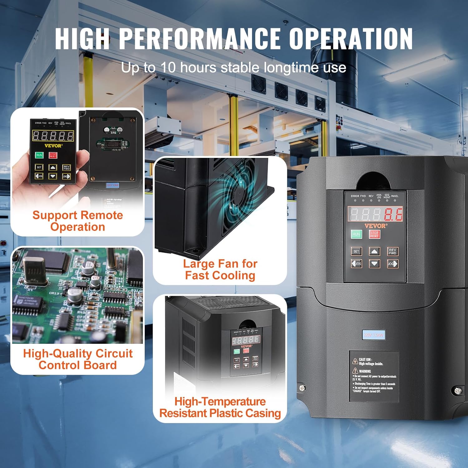
Figure 3.5: High Performance Operation Features. This image highlights the internal design elements contributing to the VFD's reliability, including a large fan for rapid cooling during prolonged use, a high-quality circuit control board, and a high-temperature resistant plastic casing. The VFD also supports remote operation via a removable panel.
4. Setup and Installation
Proper installation is crucial for the VFD's performance and longevity. The unit is designed for wall mounting.
4.1. Mounting
Mount the VFD vertically on a stable, non-flammable surface. Ensure adequate clearance around the unit for proper ventilation and heat dissipation, especially for the cooling fins and fan.
4.2. Wiring
Before wiring, ensure all power sources are disconnected. Refer to the diagram below for correct terminal connections. The VFD supports both single-phase and three-phase 220V input.

Figure 4.1: Wiring Diagram. This diagram illustrates the connection points for the VFD:
| Terminal Label | Function Description |
|---|---|
| R, T | Single phase AC 220V input terminal (or two phases of a three-phase input) |
| U, V, W | Output terminal connect to three phase motor |
| GND | Grounding terminal |
Note: For three-phase input, connect the three phases to R, S, T (if S is available, otherwise R, T, and one more input terminal). Always ensure proper grounding.
5. Operating Instructions
The VFD features an intuitive display and easy-to-use buttons for quick setup and operation.
5.1. Basic Operation
- Power On: Connect the VFD to the appropriate power supply. The LED display will illuminate.
- Start Motor: Press the RUN button to start the motor. The motor will accelerate to the set frequency.
- Stop Motor: Press the STOP/RESET button to stop the motor. The motor will decelerate and stop.
- Change Direction: Use the REV/FWD buttons to change the rotation direction of the motor while it is running or before starting.
5.2. Frequency Adjustment
The output frequency can be adjusted from 0-400 Hz. Use the JOG (Up/Down) buttons to modify the frequency directly in certain modes, or navigate through the menu to set precise values.
5.3. Menu Navigation and Parameter Setting
Press the SET button to enter the parameter setting menu. Use the JOG (Up/Down) buttons to scroll through parameters and adjust their values. Press SET again to confirm and save changes.
5.4. Remote Control
The VFD features a removable control panel that can be connected to a corresponding interface for remote control, offering enhanced convenience and flexibility in various operational setups.

Figure 5.1: Wide Compatibility. The VFD is highly versatile and compatible with a wide range of three-phase motors used in industrial machinery, including CNC routers, milling machines, and other speed-controlled equipment.
6. Maintenance
Regular maintenance ensures the optimal performance and extends the lifespan of your VFD.
- Cleaning: Periodically clean the exterior of the VFD with a soft, dry cloth. Do not use liquid cleaners or solvents. Ensure ventilation openings are free from dust and debris.
- Cooling System: The VFD is equipped with a large fan and multi-face, multi-hole design for efficient cooling. Regularly check that the fan is operating correctly and that air vents are not obstructed to prevent overheating.
- Connections: Periodically inspect all wiring connections to ensure they are secure and free from corrosion. Loose connections can lead to poor performance or damage.
- Environmental Check: Ensure the operating environment remains within the recommended temperature and humidity ranges.
7. Troubleshooting
This section provides solutions to common issues you might encounter. For problems not listed here, or if issues persist, contact VEVOR customer support.
| Problem | Possible Cause | Solution |
|---|---|---|
| VFD does not power on | No input power; Loose connections; Internal fault | Check power supply and circuit breaker. Verify all input wiring. If problem persists, contact support. |
| Motor does not run | Incorrect wiring; Overload; Fault code displayed | Verify motor wiring (U, V, W). Check for overload conditions. Refer to the display for specific fault codes and press STOP/RESET to clear. |
| Overload error | Motor load too high; Incorrect parameter settings | Reduce motor load. Check motor parameters (current, voltage) and VFD settings. Consider a higher power VFD if consistently overloaded. |
| Overheat warning | Insufficient ventilation; Ambient temperature too high; Fan malfunction | Ensure proper airflow around the VFD. Check ambient temperature. Inspect cooling fan for obstructions or malfunction. |
8. Specifications
Detailed technical specifications for the VEVOR 7.5 kW Variable Frequency Drive:

Figure 8.1: Product Dimensions and Key Specifications. This image provides a visual representation of the VFD's physical size and lists its primary technical parameters, including model number A2-8075 and M630006F.
| Parameter | Value |
|---|---|
| Model Number | A2-8075 / BPQD75KW220GF47VK7 |
| Input Voltage | 220 V (Single-phase or Three-phase) |
| Input Current | 35 A |
| Output Voltage | 220 V (Three-phase) |
| Power | 7.5 kW (10 HP) |
| Input Frequency | 40-60 Hz |
| Output Frequency | 0-400 Hz |
| Main Material | Flame-retardant ABS |
| Net Weight | 5.6 lb / 2.56 kg |
| Product Dimensions (L x W x H) | 8.6 x 5.9 x 7.0 inches / 219 x 149 x 178 mm |
| Compliance | CE |
| UPC | 197988554363 |
9. Warranty and Support
VEVOR is committed to providing high-quality products and excellent customer service. For any inquiries, technical assistance, or warranty claims, please contact VEVOR customer support. VEVOR offers attentive 24/7 support to assist you with your product needs.
Please refer to your purchase documentation or the official VEVOR website for specific warranty terms and conditions applicable to your region.
Related Documents - A2-8075 / BPQD75KW220GF47VK7
 |
VEVOR Inverter A2-8007M/A2-8015/A2-8075 User Manual and Technical Specifications Comprehensive user manual and technical specifications for VEVOR A2-8007M, A2-8015, and A2-8075 inverters, covering installation, operation, parameters, troubleshooting, and maintenance. |
 |
VEVOR D100 Series Variable Frequency Drive D0836001 Instruction Manual Explore the VEVOR D100 Series Variable Frequency Drive (VFD) D0836001 instruction manual, providing comprehensive guidance on installation, operation, safety precautions, and technical specifications for industrial and professional applications. Learn about its advanced features, wiring diagrams, and protection functions to ensure optimal performance and safe usage. |
 |
AT Series Inverter Operating Instructions - High Performance AC Motor Driver Detailed operating instructions for the AT Simple general series Inverters (AT1, AT2, AT3), covering installation, wiring, terminal descriptions, operation panel, parameter specifications, and fault codes. Features high performance and low noise for mini AC motor drivers. |
 |
Invertek Optidrive E3 IP66 AC Variable Speed Drive Quick Start Guide A quick start guide for the Invertek Optidrive E3 IP66 AC Variable Speed Drive, covering installation, wiring, operation, and troubleshooting for models ranging from 0.37kW to 22kW. |
 |
Honeywell Compact Variable Frequency Drive Installation Guide Comprehensive installation guide for the Honeywell Compact Variable Frequency Drive (Model 62-0269--02). Covers safety, mechanical and electrical installation, setup, commissioning, parameter configuration, monitoring, and fault tracing for industrial automation applications. |
 |
AT1-2.2KW (220V) Single-Phase to Three-Phase Inverter Operating Instructions Comprehensive operating instructions and technical specifications for the AT1-2.2KW (220V) single-phase to three-phase inverter, covering installation, wiring, control panel functions, parameter settings, and error codes. |
Ask a question about this manual
Ask about setup, troubleshooting, compatibility, parts, safety, or missing instructions. Manuals+ will review the question and use this page’s manual context to help answer it.