
1. Introduction
This manual provides instructions for the safe and effective use of your Guardian Hydraulic Zero Turn Lawn Mower Lift Jack. This robust lift is designed to facilitate maintenance tasks such as blade changes, cleaning, and oil service for zero-turn and riding lawn mowers. Please read this manual thoroughly before assembly or operation to ensure proper usage and to prevent injury or damage.
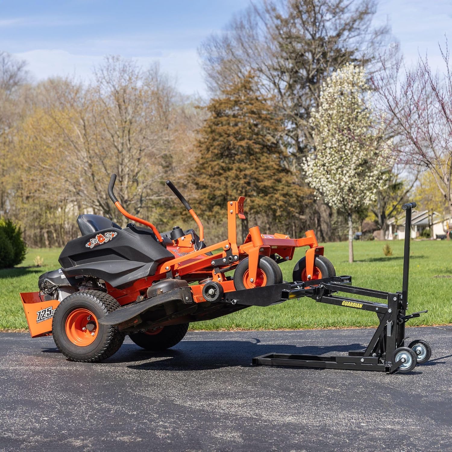
Figure 1: Guardian Zero Turn Lawn Mower Lift Jack supporting a mower for maintenance.
2. Safety Information
WARNING: Failure to follow these safety instructions may result in serious injury or property damage.
- Always ensure the lift is on a firm, level surface before operation.
- Do not exceed the maximum weight capacity of 550 lbs.
- Ensure the mower wheels are securely seated in the cradles and the pins are properly inserted before lifting.
- Never work under a raised mower without engaging all safety locking mechanisms.
- Keep hands and feet clear of moving parts during lifting and lowering.
- Do not modify the lift jack in any way. Use only original replacement parts.
- Store the lift in a safe, dry place when not in use.
- Wear appropriate personal protective equipment (PPE) such as safety glasses and gloves.
3. Assembly Instructions
The Guardian Zero Turn Lawn Mower Lift Jack requires some assembly. While the product is designed for straightforward setup, careful attention to detail is necessary. Refer to the diagrams and ensure all components are correctly installed.
3.1 Package Contents
Before beginning assembly, verify that all parts are present. If any parts are missing or damaged, contact customer support.
- Main Lift Frame with Hydraulic Pump
- Handle Assembly
- Wheel Cradles (2)
- Adjustable Extension Arms (2)
- Connecting Rods/Pins and Cotter Pins
- Wheels (4) and Axles
- Hardware (bolts, nuts, washers)
3.2 Assembly Steps
- Attach Wheels: Secure the four wheels to the main lift frame using the provided axles and hardware. Ensure wheels spin freely.
- Install Handle: Insert the handle assembly into the designated slot on the main frame and secure it with the appropriate pin or bolt.
- Connect Extension Arms: Attach the adjustable extension arms to the main frame. These arms allow for width adjustment to accommodate different mower sizes.
- Mount Wheel Cradles: Slide the wheel cradles onto the extension arms. These cradles are designed to hold the mower's front wheels. Secure them with pins.
- Hydraulic Pump Connection: Ensure the hydraulic pump mechanism is securely connected to the lifting arm of the main frame. This connection typically involves a pin and circlips. (Note: Some users have reported difficulty with circlip installation in tight spaces. An angled circlip tool may be helpful.)
- Final Check: Before first use, inspect all connections, bolts, and pins to ensure they are tight and properly secured.
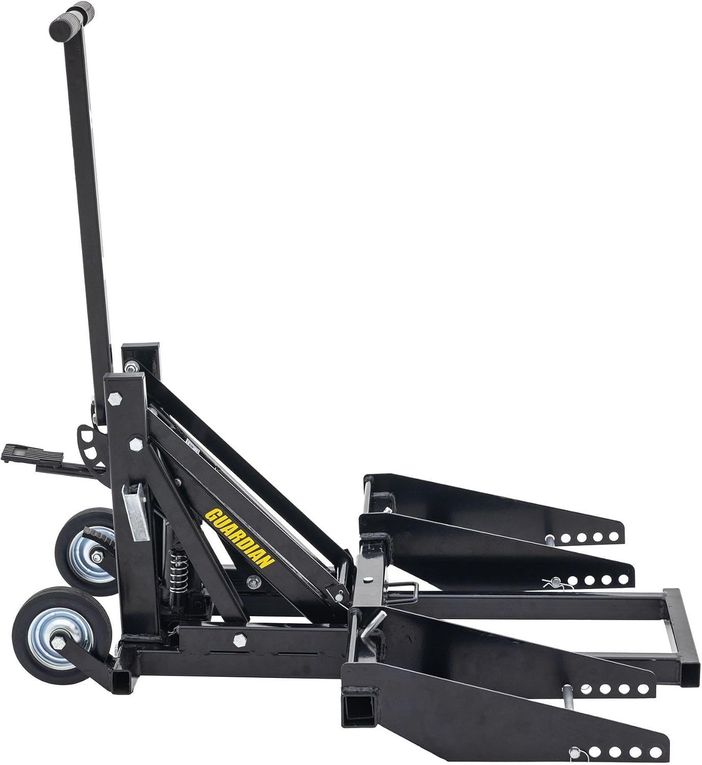
Figure 2: The lift jack in a compact state, illustrating the main frame and cradle components.

Figure 3: Detail of the adjustable wheel cradle, highlighting the mechanism for width customization.
4. Operating Instructions
Follow these steps to safely lift and lower your zero-turn or riding lawn mower.
4.1 Preparing the Mower and Lift
- Park the mower on a flat, stable surface. Engage the parking brake and turn off the engine.
- Adjust the width of the lift's wheel cradles to match the width of your mower's front wheels. The cradles accommodate wheels up to 9-7/8 inches wide and an outside wheel base up to 50.5 inches. Secure the cradles with the provided pins.
- Position the lift jack directly in front of the mower, aligning the wheel cradles with the mower's front wheels.

Figure 4: Mower wheel properly seated in the lift cradle.
4.2 Lifting the Mower
- Carefully drive the mower onto the lift's wheel cradles until the front wheels are fully seated.
- Ensure the mower is centered and stable on the cradles.
- Using the foot-operated hydraulic pump pedal, slowly pump to raise the mower. The lift has three locking height positions: 16 inches, 21.25 inches, and 27 inches.
- As the lift raises, ensure the automatic locking bolts engage fully into the desired height position. Listen for a distinct "clack" sound. Always verify both locking bolts are engaged before working under the mower.

Figure 5: The lift jack demonstrating its three adjustable locking height positions.

Figure 6: Detail of the foot-operated pump and safety locking mechanism.
4.3 Lowering the Mower
- Before lowering, ensure no tools or body parts are under the mower.
- To lower the mower, press the separate foot pedal designed for controlled lowering. This will disengage the locking mechanism and allow the hydraulic system to slowly release the lift.
- Guide the mower off the cradles once it is fully lowered to the ground.
4.4 Instructional Video
Watch this video for a visual demonstration of the Guardian Hydraulic Zero Turn Mower Lift Jack in operation, including lifting and lowering procedures.
Video 1: Demonstration of the Guardian Hydraulic Zero Turn Mower Lift Jack.
5. Maintenance
Regular maintenance ensures the longevity and safe operation of your lift jack.
- Cleaning: Keep the lift clean and free of dirt, debris, and moisture.
- Lubrication: Periodically lubricate all pivot points and moving parts with a suitable grease or oil. Pay attention to the hydraulic cylinder rod; when stored, wrap an oil-soaked rag around the exposed section to prevent corrosion.
- Inspection: Before each use, inspect the lift for any signs of damage, wear, or loose hardware. Check the hydraulic system for leaks.
- Storage: When not in use, store the lift in a dry, protected area. The cradle components can be removed for compact storage.
6. Troubleshooting
If you encounter issues with your lift jack, refer to the following common problems and solutions:
| Problem | Possible Cause | Solution |
|---|---|---|
| Lift does not raise or raises slowly. | Low hydraulic fluid, air in the system, or overloaded. | Check hydraulic fluid level and refill if necessary. Bleed air from the system (refer to hydraulic pump manual if available). Ensure load does not exceed 550 lbs. |
| Lift lowers unexpectedly. | Release valve not fully closed, hydraulic leak, or faulty locking mechanism. | Ensure the lowering pedal is not engaged. Inspect for hydraulic fluid leaks. Verify locking bolts engage correctly. Do not use if locking mechanism is faulty. |
| Mower is unstable on the lift. | Mower not centered, cradles not adjusted correctly, or uneven surface. | Reposition the mower to be centered. Adjust cradle width to fit snugly. Move the lift to a flat, stable surface. |
| Difficulty with assembly. | Unclear instructions, missing hardware, or tight tolerances. | Review assembly steps carefully. Contact customer support for missing parts. For circlips, an angled tool may assist. |
7. Specifications
- Brand: Guardian
- Model: B0DCMT9XTP
- Material: Alloy Steel
- Color: Black
- Item Weight: 108 Pounds
- Load Capacity: 550 Pounds (per axle)
- Lift Heights: 16 in, 21.25 in, 27 in (three locking positions)
- Wheel Cradle Width: Up to 9-7/8 inches
- Outside Wheel Base Adjustment: 36.25 inches to 50.5 inches
- Wheel Type: Solid 5.75 inch wheels
- UPC: 847821032960

Figure 7: Dimensional diagram of the lift jack.
8. Warranty & Support
For warranty information, technical support, or to inquire about replacement parts, please contact the seller or manufacturer directly. Refer to your purchase documentation for specific warranty terms and contact details.
Seller: Discount Ramps
Return Policy: 30-day easy returns (as per seller's policy at time of purchase).