1. Setup Guide
1.1 Unpacking and Parts Identification
Carefully unpack all components from the packaging. Verify that all parts listed in the assembly guide are present and undamaged before beginning assembly. Refer to the included parts list for identification.
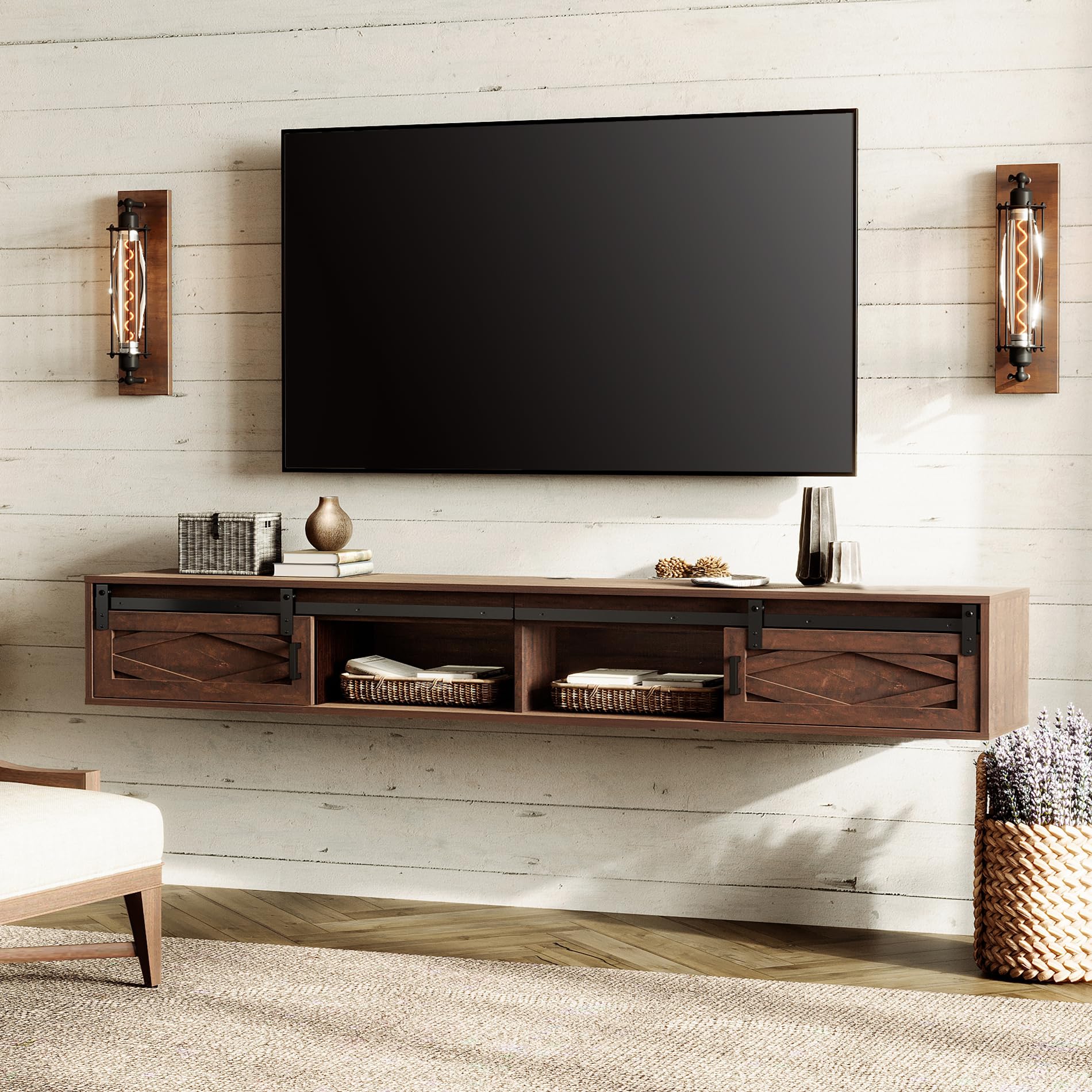
Figure 1: WAMPAT Floating TV Stand, Rustic Brown
1.2 Assembly Instructions
Follow the step-by-step assembly video for detailed visual guidance. Ensure all connections are secure before proceeding to the next step.
Video 1: WAMPAT Floating TV Stand Assembly Guide. This video provides a comprehensive walkthrough of the assembly process, from identifying parts to securing the final components.
Key Assembly Steps:
- Panel Preparation: Insert dowels and cam locks into panels (1, 4). Rotate cam locks 90 degrees to secure. Repeat for 4 instances.
- Bolt Installation: Screw bolts (A) into panels (1, 2, 3, 4, 5, 6). This step involves 35 bolts.
- Side Panel Attachment: Insert dowels (C) into panels (7, 11). Attach panels (7, 11) to panels (1, 2, 3) correctly. Insert and secure cam locks (B) to lock them. Repeat for 6 instances.
- Internal Panel Attachment: Insert dowels (C) into panels (12). Attach panels (12) to panels (1, 2, 3) correctly. Insert and secure cam locks (B) to lock them. Repeat for 6 instances.
- Additional Internal Panels: Insert dowels (C) into panels (8, 9). Attach panels (8, 9) to panels (1, 2, 3) correctly. Insert and secure cam locks (B) to lock them. Repeat for 6 instances.
- Back Panel Attachment: Attach panels (10) to panels (1, 2, 3) correctly. Insert and secure cam locks (B) to lock them. Repeat for 8 instances.
- Power Strip Installation: Insert dowels (C) into panels (5, 6). Attach panels (5, 6) to panel (4) correctly. Attach part (M) to panel (4). Attach part (O) to panel (4) with screws (L).
- Top Panel Attachment: Insert dowels (C) into panels (7, 8, 9, 11). Attach panels (4, 5, 6) to panels (7, 8, 9, 11) with screws (E). Insert and secure cam locks (8) to panels (10) to lock them. This step involves 8 dowels and 13 screws.
- Sliding Rail Installation: Secure part (13) to panel (12) with parts (H, I) correctly. Insert dowels (G) into panels (5, 6). This step involves 2 dowels, 1 part H, and 6 parts I.
- Door Installation: Place the doors (14, 15) 45 degrees onto part (G) and place it correctly. Attach parts (J) to panel (14, 15) with screws (K) correctly, but do not fix the screws tight. Adjust door height and leveling, then fix screws tight and slide doors. Attach part (M) to panel (1). This step involves 4 parts J and 8 screws K.
Wall Mounting Compatibility: This floating console shelf works with concrete walls, wooden walls, and brick walls. It will NOT work with cavity walls or gypsum board walls.
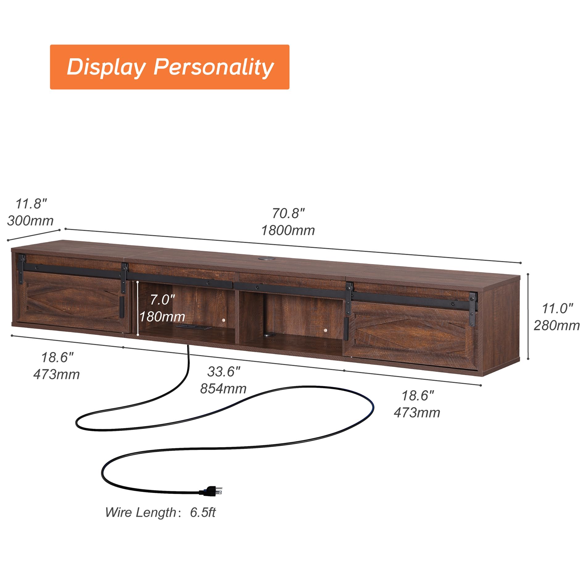
Figure 2: Wall Compatibility for Installation
2. Operating Instructions
2.1 Using the Charging Station
The integrated power strip features 4 outlets, providing convenient access for charging your TV, DVD player, phone, and other electronic devices. The shelves are designed with wire management cutouts to keep your cords organized and prevent tangling.
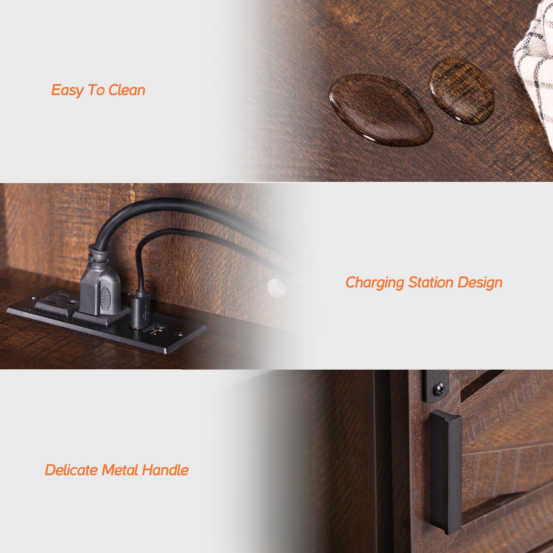
Figure 3: Integrated Charging Station
2.2 Sliding Barn Doors
The floating TV shelf features exquisite sliding barn doors that allow for flexible storage and display options. Easily slide the doors to conceal or reveal contents as needed.
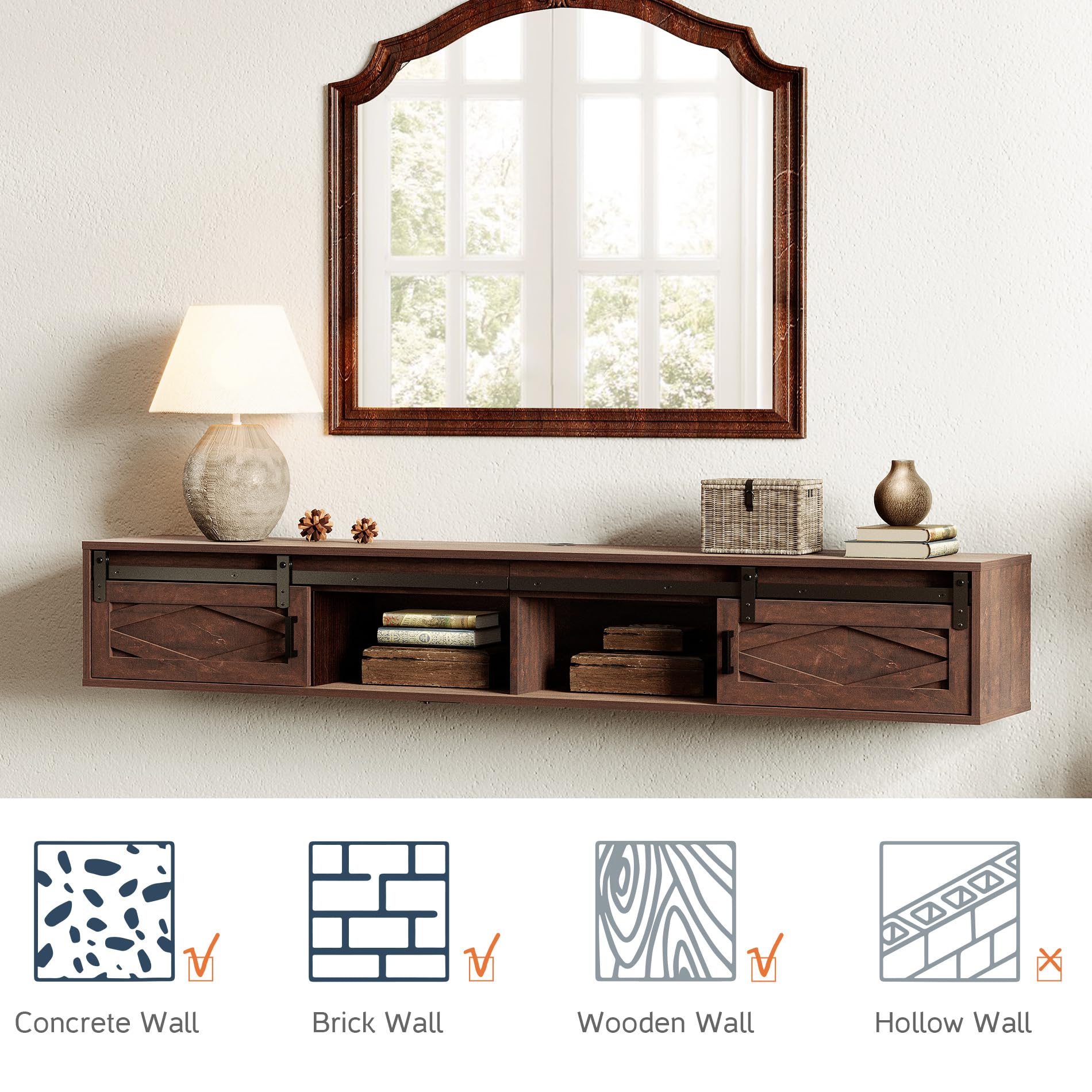
Figure 4: Sliding Barn Door Detail
3. Care and Maintenance
3.1 Cleaning
To clean the surface of the TV stand, simply wipe it with a dry cloth. Avoid using harsh chemicals or abrasive cleaners that may damage the finish.

Figure 5: Easy to Clean Surface
3.2 General Care
To ensure the longevity of your TV stand, avoid placing excessively heavy items on it, as the maximum load capacity is 80 LBS. Keep it away from direct sunlight and extreme temperature changes to prevent warping or discoloration. Periodically check all screws and connections to ensure they remain tight.
4. Troubleshooting
4.1 Common Issues
- Assembly Difficulties: If you encounter issues during assembly, double-check the instruction steps and ensure all parts are correctly oriented. Refer to the assembly video for visual clarification.
- Stability Concerns: Ensure the TV stand is securely mounted to a compatible wall type (concrete, brick, or wooden studs). Do not exceed the maximum load capacity of 80 LBS.
- Sliding Doors Not Smooth: Check that the sliding rails are clean and free of debris. Ensure the doors are properly aligned on the tracks and that all screws related to the door mechanism are tightened appropriately.
- Power Strip Not Functioning: Verify that the power strip is correctly plugged into a working wall outlet. Check for any loose connections within the unit.
5. Product Specifications
| Feature | Detail |
|---|---|
| Brand | WAMPAT |
| Model | W15E218WR |
| Material | Engineered Wood |
| Item Weight | 50.6 pounds |
| Product Dimensions | 70.8 x 11.8 x 11 inches |
| Maximum Load Capacity | 80 LBS |
| Color | Rustic Brown |
| Special Feature | Built-in Charging Station |
| Product Care Instructions | Wipe with Dry Cloth |
| FSC Certified Wood | Yes |
6. Warranty and Support
For warranty information or technical support, please refer to the contact details provided with your purchase or visit the official WAMPAT website. Ensure secure assembly and do not exceed the maximum load capacity to prevent tip-over risks.