1. Introduction
This manual provides comprehensive instructions for the safe and effective operation, maintenance, and troubleshooting of your GOYERRNES GR-CA-7200B-YC-NEW Clamp Meter Multimeter. Please read this manual thoroughly before using the device to ensure proper function and to prevent potential hazards.
The GOYERRNES GR-CA-7200B-YC-NEW is a True RMS (TRMS) digital clamp meter designed for accurate measurement of AC/DC amperage, AC/DC voltage, resistance, frequency, capacitance, continuity, diode, and temperature. It also features Non-Contact Voltage (NCV) detection and continuous data logging capabilities, making it a versatile tool for electrical diagnostics in various applications.
2. Safety Information
Always adhere to basic safety precautions when using electrical testing equipment to reduce the risk of fire, electric shock, or personal injury. Keep this manual for future reference.
- Read all instructions: Understand the operation and safety warnings before use.
- Inspect the device: Before each use, check the meter, test leads, and accessories for any damage. Do not use if damaged.
- Do not exceed ratings: Never apply voltage or current that exceeds the maximum specified ratings for the meter.
- Avoid live circuits: Do not measure current on live circuits without proper insulation and safety gear.
- Use proper terminals: Ensure test leads are connected to the correct input terminals for the desired measurement.
- Beware of high voltage: Exercise extreme caution when working with voltages above 30V AC RMS, 42V peak, or 60V DC. These voltages pose a shock hazard.
- Do not operate in explosive environments: Do not use the meter in environments with explosive gas, vapor, or dust.
- Maintain dry conditions: Keep the meter dry. Do not operate in wet or damp conditions.
- Service by qualified personnel: Repairs or servicing should only be performed by qualified service personnel.
3. Product Features
The GOYERRNES GR-CA-7200B-YC-NEW Clamp Meter Multimeter offers a range of features for comprehensive electrical testing:
- Versatile Measurement: Accurately measures AC/DC Amperage, AC/DC Voltage, Resistance, Frequency or Duty Cycle, Capacitance, and Temperature (℃/℉).
- Non-Contact Voltage (NCV) Detection: Provides a safe method for detecting AC voltage without direct contact.
- Diode and Continuity Tests: Essential functions for circuit diagnostics.
- Continuous Data Logging: Displays AC/DC amps, volts, ohms, capacitance, Hz, and temperature in Max/Min/Avg on the same interface with real-time readings. Includes a curve graph for visual trend analysis.
- High Accuracy: Features 0.1 amp resolution for 0.1 ~ 60A AC/DC current and 1A for 60 ~ 400A, supporting precise current measurements.
- Large Digital Display: Backlit LCD ensures visibility in dimly lit areas.
- Wide Temperature Range: Extensible thermocouple probe supports temperature measurements from -4 to 1832℉ (-20 to 1000℃).
- Jaw Caliber Size: 1.77 inches (45mm) for clamping around conductors.
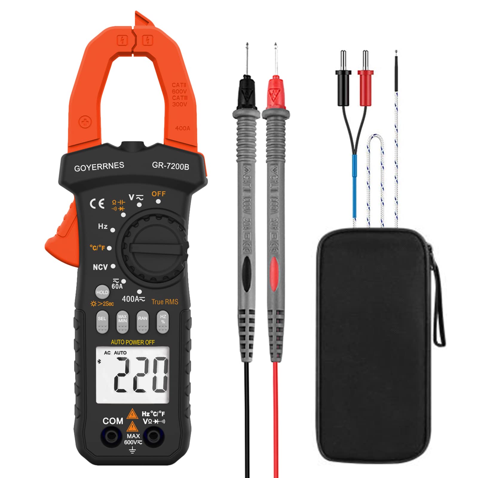
Figure 1: Front view of the GOYERRNES GR-CA-7200B-YC-NEW Clamp Meter Multimeter, showing the display, function dial, and current clamp jaw.
4. Device Layout
Familiarize yourself with the main components of your clamp meter:
- Current Clamp Jaw: Used for non-contact AC/DC current measurement.
- Function Dial: Selects the desired measurement mode (e.g., Voltage, Resistance, Amperage).
- LCD Display: Shows measurement readings, units, and various indicators. Backlit for low-light conditions.
- Input Jacks: Terminals for connecting test leads for voltage, resistance, capacitance, diode, continuity, and temperature measurements.
- Hold/Backlight Button: Freezes the current reading on the display and activates/deactivates the backlight.
- Range/Mode Button: Switches between auto-ranging and manual ranging, or selects sub-functions within a mode (e.g., AC/DC voltage).
- NCV Sensor: Located at the top of the meter for non-contact voltage detection.
Figure 2: Detailed view of the clamp meter, highlighting the display, function dial, and input terminals.
5. Setup
5.1 Battery Installation
- Ensure the meter is powered off.
- Locate the battery compartment cover on the back of the meter.
- Use a screwdriver to loosen the screw(s) and remove the cover.
- Insert new batteries, observing the correct polarity (+ and -).
- Replace the battery compartment cover and secure it with the screw(s).
5.2 Initial Checks
Before first use, and periodically thereafter, perform the following checks:
- Verify that the meter and test leads are free from any physical damage.
- Ensure the battery is properly installed and has sufficient charge.
- Test the continuity function on a known good conductor to confirm basic operation.
6. Operating Instructions
6.1 Power On/Off
Rotate the function dial from the "OFF" position to any desired measurement function to power on the meter. To power off, rotate the dial back to the "OFF" position.
6.2 AC/DC Voltage Measurement
- Insert the red test lead into the "VΩHz" jack and the black test lead into the "COM" jack.
- Rotate the function dial to the "V~" (AC Voltage) or "V-" (DC Voltage) position.
- Connect the test probes in parallel to the circuit or component you wish to measure.
- Read the voltage value on the LCD display.
6.3 AC/DC Current Measurement (Clamp Function)
Important Safety Note: To measure current with the clamp function, you MUST separate the hot and neutral conductors and clamp around only the LIVE wire. Clamping around both wires will result in a zero amp reading as the currents cancel each other out. For convenience without stripping wires, use an AC Line Splitter.
- Rotate the function dial to the "A~" (AC Current) or "A-" (DC Current) position.
- Press the jaw trigger to open the clamp jaw.
- Enclose a single conductor (live wire) within the clamp jaw.
- Release the trigger to close the jaw securely around the conductor.
- Read the current value on the LCD display.
6.4 Resistance Measurement
- Insert the red test lead into the "VΩHz" jack and the black test lead into the "COM" jack.
- Rotate the function dial to the "Ω" (Resistance) position.
- Ensure the circuit or component under test is de-energized.
- Connect the test probes across the component.
- Read the resistance value on the LCD display.
6.5 Capacitance Measurement
- Insert the red test lead into the "VΩHz" jack and the black test lead into the "COM" jack.
- Rotate the function dial to the "CAP" (Capacitance) position.
- Ensure the capacitor is fully discharged before testing to prevent damage to the meter.
- Connect the test probes across the capacitor terminals.
- Read the capacitance value on the LCD display.
6.6 Frequency/Duty Cycle Measurement
- Insert the red test lead into the "VΩHz" jack and the black test lead into the "COM" jack.
- Rotate the function dial to the "Hz" (Frequency) position.
- Connect the test probes in parallel to the circuit where you want to measure frequency or duty cycle.
- Read the frequency (Hz) or duty cycle (%) value on the LCD display.
6.7 Diode Test
- Insert the red test lead into the "VΩHz" jack and the black test lead into the "COM" jack.
- Rotate the function dial to the "Diode" position.
- Connect the red probe to the anode and the black probe to the cathode of the diode.
- The display will show the forward voltage drop. Reverse the probes; the display should show "OL" (Open Loop) for a good diode.
6.8 Continuity Test
- Insert the red test lead into the "VΩHz" jack and the black test lead into the "COM" jack.
- Rotate the function dial to the "Continuity" position (often shared with resistance or diode).
- Connect the test probes across the circuit or component.
- If continuity exists (low resistance), the meter will emit an audible beep and display a low resistance value.
6.9 Non-Contact Voltage (NCV) Detection
- Rotate the function dial to the "NCV" position.
- Move the NCV sensor (located at the top of the meter) close to the conductor or outlet you suspect has AC voltage.
- The meter will indicate the presence of AC voltage through audible beeps and/or visual indicators on the display.
6.10 Temperature Measurement
- Insert the thermocouple probe into the designated temperature input jacks (usually marked with "TEMP" or similar, or shared with VΩHz/COM with specific polarity).
- Rotate the function dial to the "TEMP" (Temperature) position.
- Place the tip of the thermocouple probe on or near the object whose temperature you wish to measure.
- Read the temperature value (in ℃ or ℉) on the LCD display.
6.11 Data Logging (Max/Min/Avg)
This meter supports continuous data logging, displaying maximum, minimum, and average readings on the same interface. A curve graph visually represents changes over time. Refer to the specific button on your device (often labeled "MAX/MIN" or similar) to activate and cycle through these modes. Data logging rates may be adjustable.
7. Maintenance
7.1 Cleaning
Wipe the meter's casing with a damp cloth and a mild detergent. Do not use abrasives or solvents. Ensure the meter is completely dry before use.
7.2 Storage
When not in use for extended periods, remove the batteries to prevent leakage. Store the meter in a cool, dry place, away from direct sunlight and extreme temperatures.
7.3 Battery Replacement
When the low battery indicator appears on the display, replace the batteries as described in Section 5.1. Use only the specified battery type.
8. Troubleshooting
If you encounter issues with your clamp meter, refer to the following common problems and solutions:
- No Display/Meter Not Powering On:
- Check battery installation and polarity.
- Replace with fresh batteries.
- Ensure the function dial is not in the "OFF" position.
- Incorrect Readings:
- Verify the correct measurement function is selected.
- Ensure test leads are properly connected to the correct input jacks.
- For current measurement, ensure the clamp is around a single live conductor only.
- Check for damaged test leads or probes.
- "OL" (Overload) Display:
- The measured value exceeds the meter's range for the selected function. Select a higher range if available, or ensure the input is within the meter's specifications.
- No NCV Detection:
- Ensure the NCV function is selected and the sensor is close enough to the AC voltage source.
- The voltage may be too low to detect.
9. Specifications
| Specification | Value |
|---|---|
| Brand | GOYERRNES |
| Model Number | GR-CA-7200B-YC-NEW |
| Measurement Type | Ammeter (Multimeter functions included) |
| Power Source | Battery Powered |
| Upper Temperature Rating (Thermocouple) | 1832 Degrees Fahrenheit (1000 Degrees Celsius) |
| Jaw Caliber Size | 1.77 inches (45mm) |
| AC/DC Current Resolution (0.1-60A) | 0.1A |
| AC/DC Current Resolution (60-400A) | 1A |
| Specification Met | CSA |
| Included Components | Clamp meter |
10. Warranty and Support
10.1 Warranty Information
This GOYERRNES Clamp Meter Multimeter is covered by a 2-YEAR warranty from the date of purchase. This warranty covers defects in materials and workmanship under normal use. It does not cover damage resulting from misuse, abuse, accident, unauthorized alteration, or improper installation.
10.2 Customer Support
For technical assistance, warranty claims, or product inquiries, please contact GOYERRNES customer support through the retailer's platform or the official GOYERRNES website. Please have your model number (GR-CA-7200B-YC-NEW) and purchase date available when contacting support.