1. Introduction
This manual provides detailed instructions for the installation, operation, and maintenance of the KACOME A5882-4260 Brushless DC Worm Gear Motor. This motor is designed for applications requiring adjustable speed, high torque, and reliable performance.
Key features include:
- Speed Adjustment: Utilizes a reducer to adjust motor speed, suitable for applications with lower speed requirements such as urban water supply systems and fans.
- Increased Output Torque: Converts high-speed, low-torque output to low-speed, high-torque output, essential for lifting equipment, mixers, and conveyor systems.
- Load Protection: Designed to protect the connected load in industrial production environments.
- Versatile Application: Widely used in metallurgy, mining, lifting, transportation, cement, construction, chemical, textile, and printing and dyeing industries.
2. Specifications
The following table outlines the general specifications for the A5882-4260 motor. For detailed performance parameters, refer to the "Parameter Table" image.
| Parameter | Value |
|---|---|
| Model | A5882-4260 |
| Voltage Range | 6-24V DC |
| Rated Voltage | 12V / 24V DC |
| Continuous Current | 0.6A (No Load) |
| Output Power | 20W |
| Max Torque | 90 kg.cm (Stall Torque) |
| Construction | Permanent Magnet |
| Commutation | Brushless |
| Protection Function | Anti-drip |
| Efficiency | IE 1 |
| Service Life | 2000 hours |
| Item Weight | 2.2 pounds (approx. 1000g) |
| Package Dimensions | 1.18 x 0.79 x 0.39 inches |
| Worm Gear | Mechanical self-locking |
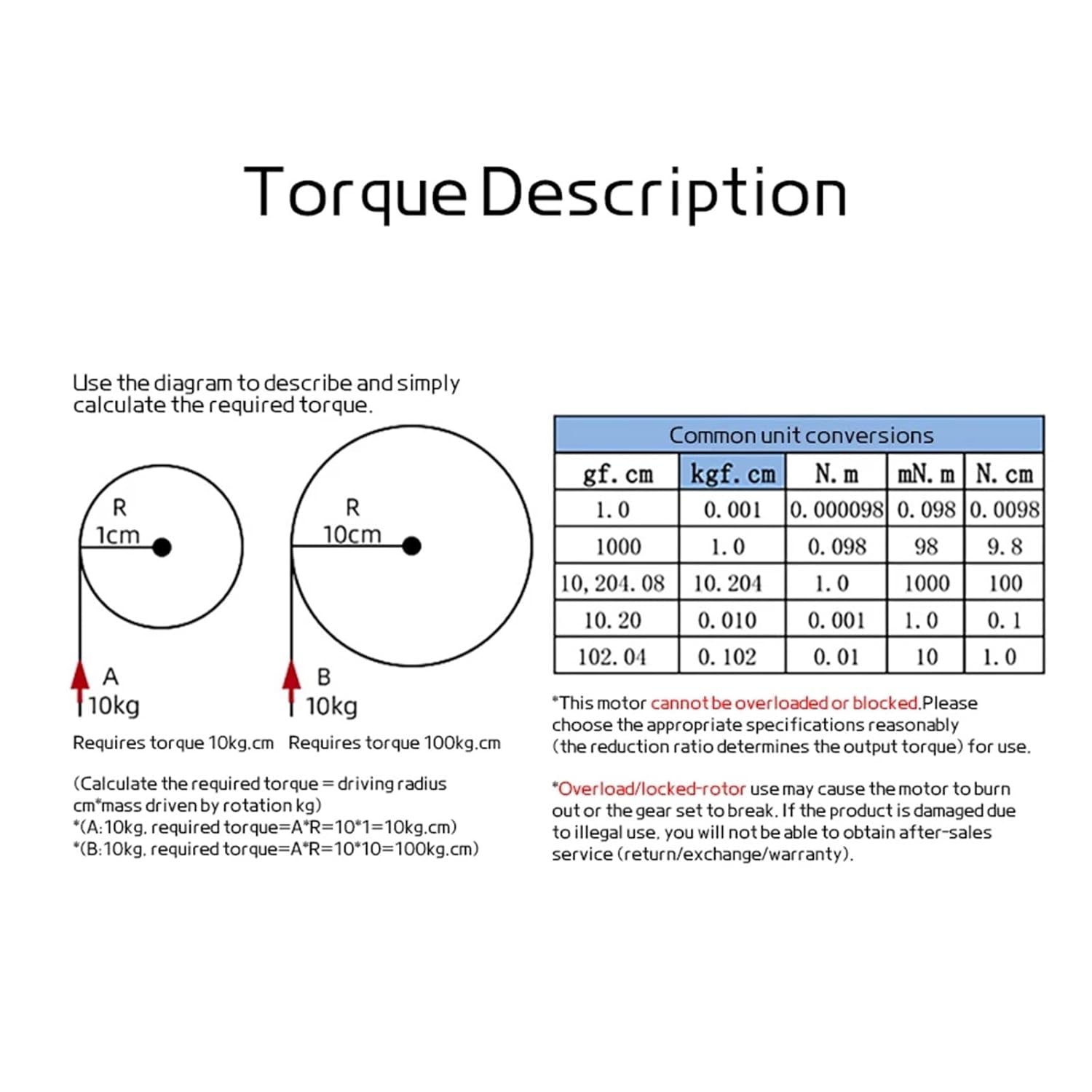
Figure 2.1: Parameter Table. This table details the no-load speed, load current, load speed, load torque, stall torque, and reduction ratios for various voltage and RPM configurations. Note: Reduce all parameters by half when connected to 12V voltage.
3. Setup and Installation
Proper installation is crucial for the optimal performance and longevity of your motor. Follow these guidelines:
- Mounting: Securely mount the motor using appropriate fasteners. Refer to the "Product Size" and "Support Size" diagrams for dimensions and mounting hole patterns.
- Power Connection: Connect the motor to a DC power supply within the 6-24V range. Ensure correct polarity for desired rotation direction. The motor supports both 12V and 24V operation.
- Load Attachment: Connect the load to the output shaft. Ensure the load is within the motor's torque capabilities to prevent damage. The output shaft is customizable.
- Environmental Considerations: Install the motor in a clean, dry environment. The motor has an anti-drip protection function.

Figure 3.1: Product Size. This diagram illustrates the overall dimensions of the A5882-4260 motor, including shaft length and mounting points. All dimensions are in millimeters.

Figure 3.2: Support Size. This diagram provides dimensions for a compatible mounting bracket, showing hole spacing and overall bracket size for secure installation.
4. Operation
The A5882-4260 motor offers adjustable speed and forward/reverse capabilities. Follow these instructions for safe and effective operation:
- Power On/Off: Apply the specified DC voltage (6-24V) to power the motor. Disconnect power to stop operation.
- Speed Adjustment: The motor's speed can be adjusted by varying the input voltage or by using an external speed controller (not included). Refer to the Parameter Table for speed ranges at different voltages.
- Forward and Reverse: The motor supports forward and reverse operation. This is typically controlled by reversing the polarity of the input voltage. Consult your specific wiring diagram for details.
- Torque Considerations: The motor provides high torque output. Understand the torque requirements of your application. Refer to the "Torque Description" for calculations and unit conversions.

Figure 4.1: Torque Description. This diagram explains how to calculate required torque based on driving radius and load, and provides common unit conversions for torque measurements. It also includes a critical warning regarding motor overload.
Important Warning: This motor cannot be overloaded or blocked. Overload or a blocked rotor may cause the motor to burn out or the gear set to break. Please choose appropriate specifications and reduction ratios to match your application's output torque requirements. Damage due to illegal use will not be covered by after-sales service (return/exchange/warranty).
5. Maintenance
The A5882-4260 motor is designed for durability with a service life of approximately 2000 hours. Regular maintenance can further extend its operational life:
- Keep Clean: Periodically clean the motor's exterior to prevent dust and debris accumulation, which can affect cooling and performance.
- Inspect Connections: Regularly check all electrical connections for tightness and signs of corrosion.
- Avoid Overload: Ensure the motor is not continuously operated beyond its rated load and torque specifications. Refer to the Parameter Table and Torque Description.
- Lubrication: The internal gears are pre-lubricated. Avoid disassembling the gear housing unless absolutely necessary, as this can compromise the sealing and lubrication.

Figure 5.1: Internal Components. This exploded view shows the internal structure of the motor, including the internal pure copper coil, brass worm, metal case, gear, screw, and customizable output shaft. This diagram is for informational purposes regarding internal construction.
6. Troubleshooting
If you encounter issues with your A5882-4260 motor, refer to the following common problems and solutions:
| Problem | Possible Cause | Solution |
|---|---|---|
| Motor does not start | No power supply, incorrect wiring, power supply voltage too low, motor overloaded. | Check power connections and voltage. Verify wiring polarity. Reduce load if applicable. |
| Motor runs slowly or with reduced torque | Motor overloaded, power supply voltage too low, internal friction. | Reduce load. Increase power supply voltage (within limits). Check for obstructions. |
| Motor makes unusual noise | Mechanical obstruction, worn gears, improper mounting. | Inspect for obstructions. Ensure secure mounting. If noise persists, contact support. |
| Motor overheats | Continuous overload, insufficient ventilation, high ambient temperature. | Reduce load or duty cycle. Ensure adequate ventilation around the motor. |
7. Warranty and Support
The KACOME A5882-4260 motor comes with a standard return policy of 30 days. For specific warranty details and support, please refer to your purchase documentation or contact the seller directly.
Important: Damage resulting from overload, blocked rotor, or improper use as described in this manual will void the warranty and after-sales service.
For technical assistance or inquiries, please contact your point of purchase or the manufacturer, KACOME.