
CCH-CS12-E4-P00QE
User Manual
Corning CCH-CS12-E4-P00QE Fiber Optic Splice Cassette
1. Introduction
This manual provides comprehensive instructions for the installation, operation, and maintenance of the Corning CCH-CS12-E4-P00QE Fiber Optic Splice Cassette. This product is designed to facilitate efficient and reliable fiber optic cable management and splicing within compatible CCH housings. Please read this manual thoroughly before proceeding with installation or operation to ensure proper use and optimal performance.
2. Product Overview
The Corning CCH-CS12-E4-P00QE is a 12-fiber LC duplex multimode 50µm OM4 pigtailed splice cassette. It is engineered to streamline fiber optic installations by offering a preloaded and pre-routed solution for quick fusion splicing. Its modular design allows for easy management and access to fibers within the housing without disturbing other connections.
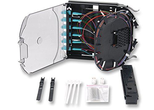
Figure 2.1: The Corning CCH-CS12-E4-P00QE Fiber Optic Splice Cassette shown open, revealing the internal fiber routing and LC duplex connectors. Various installation accessories are also visible.

Figure 2.2: The splice cassette as it appears in its retail packaging, displaying the product label with model number and specifications.

Figure 2.3: A detailed view of the LC duplex connectors integrated into the cassette, highlighting the precision and quality of the fiber terminations.
Key Features:
- Modular Design: Enables efficient cable slack management within CCH panels.
- Pre-prepped for Splicing: Comes preloaded and pre-routed with a 2-meter pigtail assembly, significantly reducing field labor.
- Enhanced Durability: Features 900 µm jacket at the connector panel for added fiber protection.
- Ease of Splicing: Colored 250 µm fibers at the splice point facilitate quick identification and preparation.
- Integrated Strain Relief: Strain relief is pre-applied from the manufacturing facility, with additional grommets and cable ties included.
- Flexible Splicing Environment: Allows splicing to be performed away from the rack housing in a suitable workspace.
- Simplified Management: Eliminates the need for separate splice trays or housings.
3. Setup and Installation
The CCH-CS12-E4-P00QE cassette is designed for straightforward installation into Corning CCH housings. Follow these steps for proper setup:
- Unpacking and Inspection: Carefully remove the splice cassette from its packaging. Verify that all components are present, including the pigtailed CCH adapter panel, rails (one for CCH-01U/2U/3U housings, two for CCH-04U housings), grommets, cable ties, protective braided tubing, and heat-shrink splice protectors. Inspect for any visible damage.
- Housing Preparation: Ensure your CCH housing is ready for cassette installation. Refer to your CCH housing manual for specific preparation steps.
- Cassette Mounting:
- For CCH-01U/2U/3U housings, attach the single rail to the cassette as per the housing's instructions.
- For CCH-04U housings, attach both rails to the cassette.
- Slide the prepared cassette into the designated slot within the CCH housing until it clicks securely into place.
- Incoming Cable Routing:
Route the incoming fiber optic cable into the CCH housing. Utilize the provided protective braided tubing for the incoming cable to prevent abrasion and damage. Secure the cable using the supplied grommets and cable ties to ensure proper strain relief.

Figure 3.1: Installation diagrams illustrating routing for 1U/2U/3U housings, pigtail management, splice tray layout, and incoming cable layer. For detailed 4U routing, refer to the official Corning SRP 003-895 document.
For detailed routing instructions, especially for 4U housings, refer to the official Corning document: Corning SRP 003-895 (PDF).
- Fiber Preparation for Splicing: The cassette comes with 250 µm colored fibers for ease of identification. Carefully prepare these fibers for fusion splicing according to standard fiber optic splicing procedures. The 900 µm jacket at the connector panel provides added durability during handling.
4. Operating Instructions (Splicing)
The CCH-CS12-E4-P00QE cassette is designed for efficient fusion splicing of individual or ribbon fibers. Its pre-routed design simplifies the process.
- Accessing Fibers: The modular design allows you to access the fibers within an individual cassette without disturbing other fibers in the housing. Gently open the cassette cover to expose the splice area.
- Splicing Procedure:
- Perform fusion splicing of the incoming fibers to the pre-routed pigtails within the cassette. Ensure proper fiber cleaving and fusion parameters for optimal splice loss.
- Utilize the provided heat-shrink splice protectors to protect each splice point immediately after fusion.
- The colored 250 µm fibers aid in correct fiber pairing and splicing.
- Splice Management: After splicing and protecting, carefully route the spliced fibers and splice protectors within the designated channels of the cassette. The cassette is designed to manage all splices internally, eliminating the need for external splice trays.
- Closing the Cassette: Once all splicing and fiber management are complete, securely close the cassette cover. Ensure no fibers are pinched or stressed.
Note: Splicing can be performed with the cassette removed from the rack housing in a suitable workspace, offering greater flexibility during installation.
5. Maintenance
The Corning CCH-CS12-E4-P00QE splice cassette requires minimal maintenance due to its robust design. However, periodic checks and proper handling are crucial for long-term performance.
- Cleaning Connectors: If the LC duplex connectors are exposed or disconnected, ensure they are cleaned using appropriate fiber optic cleaning tools and solutions before re-connection to prevent signal degradation.
- Fiber Inspection: Periodically inspect exposed fibers and pigtails for any signs of damage, kinks, or excessive bending.
- Cable Management: Ensure that all incoming and outgoing cables within the housing remain properly routed and secured with strain relief to prevent stress on the fibers.
- Moves, Adds, and Changes (MACs): The modular design facilitates easy re-access for MACs. When performing such operations, exercise caution to avoid disturbing adjacent fibers or existing splices.
6. Troubleshooting
This section addresses common issues that may arise during the installation or operation of the fiber optic splice cassette.
| Problem | Possible Cause | Solution |
|---|---|---|
| High Signal Loss / No Signal |
|
|
| Cassette does not fit into housing |
|
|
| Fibers difficult to manage within cassette |
|
|
7. Specifications
| Attribute | Value |
|---|---|
| Model Number | CCH-CS12-E4-P00QE |
| Fiber Count | 12 Fibers |
| Connector Type | LC Duplex |
| Fiber Type | Multimode 50µm OM4 |
| Cable Type | Fibre Optic |
| Product Dimensions | 12 x 8 x 3 inches |
| Item Weight | 3 Pounds |
| Compatible Devices | Server, Router, Network Switch |
| Special Feature | Braided (referring to protective tubing) |
| Manufacturer | Corning (as per product branding) |
| Date First Available | January 5, 2016 |
| ASIN | B0DC4NCY14 |
8. Warranty and Support
Information regarding the specific warranty terms for the Corning CCH-CS12-E4-P00QE Fiber Optic Splice Cassette was not available in the provided product data. For detailed warranty information, technical support, or service inquiries, please contact Corning directly through their official website or customer service channels.
You may find additional resources and contact information on the official Corning website: www.corning.com
Ask a question about this manual
Ask about setup, troubleshooting, compatibility, parts, safety, or missing instructions. Manuals+ will review the question and use this page’s manual context to help answer it.