1. Product Overview
The WENBIXIA 320 series inverter is a versatile variable frequency drive (VFD) designed for precise control of three-phase motor speed. It features low noise operation, voltage vector and V/F control, quick response, and accurate torque management. This VFD supports automatic tuning of motor parameters, online switching between automatic and torque control, and includes a simple PLC function with 17 types of fault protection.
Key features include:
- Dual analog input for flexible control.
- Comprehensive protection against overcurrent, overvoltage, overload, phase loss, and short circuits.
- Simple PLC function for automated tasks.
- Output voltage regulation (AVR) function.
- Multiple speed setting methods and rich I/O terminals.
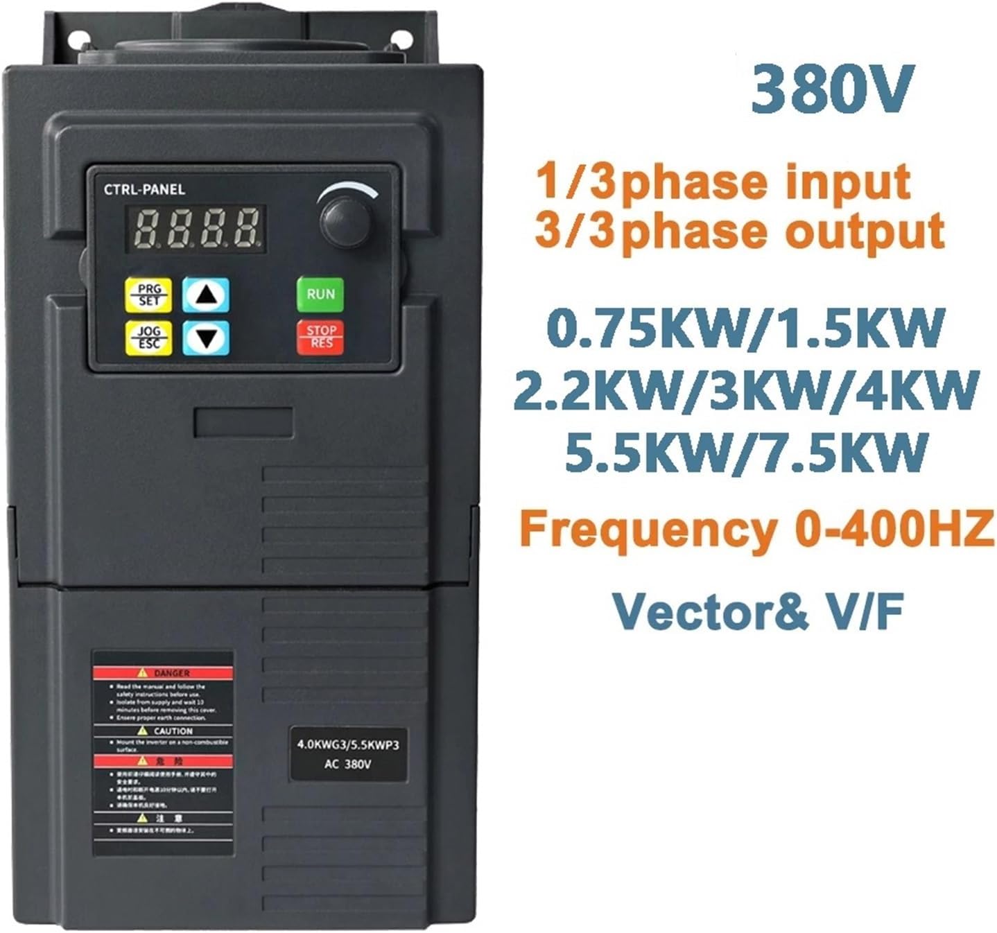
Figure 1: Front view of the WENBIXIA VFD 320 Series, showing the control panel, display, and key specifications like input/output phases, power ratings (0.75KW to 7.5KW), and frequency range (0-400Hz).
2. Installation and Wiring
Proper installation and wiring are crucial for the safe and efficient operation of the VFD. Ensure all connections are secure and follow local electrical codes.
2.1 Mounting
The VFD casing is designed with multiple ventilation holes to ensure adequate cooling and extend service life. Mount the unit in a location that allows for proper airflow and prevents overheating.

Figure 2: Angled view of the VFD, highlighting the cooling fins and ventilation design for optimal heat dissipation.

Figure 3: Rear view of the VFD, illustrating the mounting points and internal capacitor components.
2.2 Electrical Connections
Refer to the wiring diagram and terminal descriptions below for correct electrical connections. Always disconnect power before wiring.

Figure 4: Detailed wiring diagram for the VFD, showing connections for power input (R, S, T), motor output (U, V, W), grounding (PE), and control terminals (X1-X5, GND, AVI, 10V, ACI, A0, TA, TB, TC). Below the diagram is a table describing each terminal's function and default settings.
Terminal Descriptions:
| Terminal | Function | Setting and Description |
|---|---|---|
| R, S, T | Power supply of AC Drive | For 380V models, connect to R, S, T terminals. An overcurrent protection device should be used at the input. |
| U, V, W | AC drive output, connected to the motor | To reduce leakage current, the motor connecting cable should not exceed 50m. |
| PE | Grounding | The AC drive must be well grounded. |
| X1 | Digital input X1 | Set via parameter F5.02, default is FWD. |
| X2 | Digital input X2 | Set via parameter F5.03, default is REV. |
| X3 | Digital input X3 | Set via parameter F5.04, default is set to Multi-speed Step 1. |
| X4 | Digital input X4 | Set via parameter F5.05, default is set to Multi-speed Step 2. |
| X5 | Digital input X5 | Set via parameter F5.06, default is set to external reset signal. |
| GND | Common port of signal | Zero potential of input/output signal. |
| AVI | 0-10V signal input | 0-10V. |
| 10V | Frequency set potentiometer power supply | +10V, max. 10mA. |
| ACI | 4-20mA analog input | 4-20mA. |
| A0 | Analog output signal | Set via parameter F6.10. |
| TA, TB, TC | Relay output | Set via parameter F5.07. Contact capacity: AC 250V/3A, DC 24V/2A. |
The terminal block is easily accessible by removing screws. Ensure all wires are connected firmly.

Figure 5: Front view of the VFD with the terminal block cover open, showing the screw terminals for electrical connections.
3. Operation
The WENBIXIA VFD 320 Series features a user-friendly control panel for easy operation and parameter adjustment.
3.1 Control Panel Overview
The control panel includes a digital display, function buttons, and a rotary encoder for setting parameters.
- Display: Shows current frequency, output voltage, current, and fault codes.
- PRG/SET Button: Enters/exits parameter setting mode and confirms selections.
- JOG/ESC Button: Initiates jog operation and cancels current operation or exits menus.
- Up/Down Arrows: Navigate through menus and adjust parameter values.
- RUN Button: Starts the motor.
- STOP/RES Button: Stops the motor and resets fault conditions.
- Rotary Encoder: Used for fine-tuning frequency and parameter values.
3.2 Basic Operation Steps
- Power On: Ensure all wiring is correct and secure, then apply power to the VFD.
- Parameter Setting (if needed):
- Press the PRG/SET button to enter parameter setting mode.
- Use the Up/Down Arrows or Rotary Encoder to navigate to the desired parameter (e.g., motor parameters, frequency settings).
- Press PRG/SET again to select the parameter.
- Adjust the value using the Up/Down Arrows or Rotary Encoder.
- Press PRG/SET to save the new value.
- Press JOG/ESC to exit parameter setting mode.
- Start Motor: Press the RUN button to start the motor. The display will show the operating frequency.
- Adjust Speed: Use the Rotary Encoder to adjust the output frequency and thus the motor speed during operation.
- Stop Motor: Press the STOP/RES button to stop the motor.
For advanced functions like simple PLC, torque control, or external control via I/O terminals, refer to the detailed parameter manual (not included here) for specific parameter settings.
4. Maintenance
Regular maintenance ensures the longevity and reliable performance of your WENBIXIA VFD.
- Cleaning: Keep the VFD clean and free from dust and debris. Use a soft, dry cloth for cleaning. Do not use liquid cleaners.
- Ventilation: Ensure that the ventilation openings are not blocked. Periodically check and clean the cooling fan if accessible, to prevent overheating.
- Connections: Periodically check all electrical connections for tightness. Loose connections can cause overheating or intermittent operation.
- Environment: Operate the VFD within its specified environmental conditions (temperature, humidity, dust level) to prevent damage.
- Inspection: Visually inspect the VFD for any signs of damage, discoloration, or unusual odors.
5. Troubleshooting
This section provides basic troubleshooting steps for common issues. For complex problems or persistent faults, contact technical support.
| Problem | Possible Cause | Solution |
|---|---|---|
| VFD does not power on | No input power; Incorrect wiring; Blown fuse. | Check power supply; Verify input wiring (R, S, T); Check fuses. |
| Motor does not run | Incorrect motor wiring (U, V, W); Fault condition; Parameter settings incorrect. | Verify motor connections; Check for fault codes on display and reset; Review motor parameters. |
| Overcurrent fault | Motor overload; Short circuit in motor or wiring; Acceleration time too short. | Reduce motor load; Check motor and wiring for shorts; Increase acceleration time parameter. |
| Overvoltage fault | Input voltage too high; Deceleration time too short; Regenerative load. | Check input voltage; Increase deceleration time parameter; Consider braking resistor for regenerative loads. |
| Overload fault | Motor or VFD overloaded; Motor parameters incorrect. | Reduce load; Check motor current and VFD capacity; Verify motor parameters (e.g., F0.03, F0.04). |
The VFD provides 17 kinds of fault protection. When a fault occurs, a corresponding fault code will be displayed. Refer to the full product manual for a complete list of fault codes and their specific remedies.
6. Specifications
Below are the general specifications for the WENBIXIA 320 Series VFD. Specific power ratings vary by model variant.
- Input Voltage: 3-phase 380V (for this model variant)
- Output Voltage: 3-phase 0-380V
- Power Range: 0.75KW, 1.5KW, 2.2KW, 3KW, 4KW, 5.5KW, 7.5KW (model dependent)
- Frequency Range: 0-400Hz
- Control Mode: Voltage Vector & V/F Control
- Protection: Overcurrent, Overvoltage, Overload, Phase Loss, Short Circuit
- Analog Input: Dual analog input (0-10V, 4-20mA)
- Digital Inputs: Multiple configurable digital inputs
- Relay Output: Yes (AC 250V/3A, DC 24V/2A)
- Item Weight: Approximately 2.2 pounds (for 2.2KW model)
- Package Dimensions: Approximately 1.18 x 0.79 x 0.39 inches