1. Introduction
This manual provides essential information for the safe and efficient operation of your LVSEDTAL MT6070i 7-Inch HMI Touch Panel. Please read this manual thoroughly before installation, operation, or maintenance to ensure proper usage and to prevent damage to the device or injury to personnel.
The MT6070i is a Human Machine Interface (HMI) designed for industrial applications, featuring a 7-inch TFT display with 800*480 resolution, a resistive touch panel, and an Ethernet port. It is compatible with various PLCs and intelligent controllers, offering low power consumption, fast operation speed, and stable performance.
2. Safety Information
- Always disconnect power before performing any installation, wiring, or maintenance.
- Ensure proper grounding to prevent electrical shock.
- Do not expose the device to excessive moisture, dust, or extreme temperatures.
- Only qualified personnel should perform installation and wiring.
- Use appropriate personal protective equipment (PPE) when handling the device.
- Avoid strong impacts or vibrations to the device.
3. Product Overview
The LVSEDTAL MT6070i HMI Touch Panel is designed for robust industrial environments, offering a clear display and intuitive touch interface for controlling and monitoring various systems.
3.1 Key Features
- 7-inch TFT display with 800x480 resolution
- 4-wire resistive touch panel
- Ethernet communication port
- Low power consumption and stable performance
- Wide compatibility with PLCs and intelligent controllers
3.2 Device Components (Rear View)
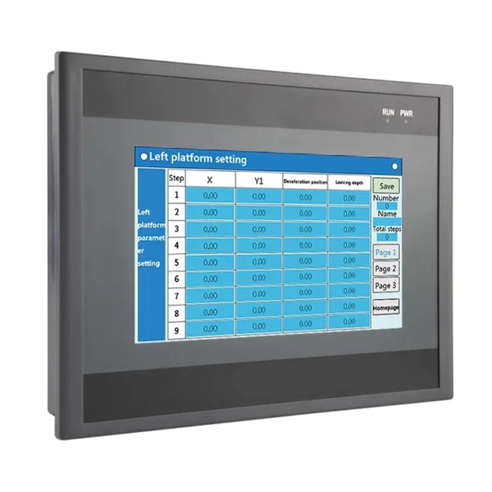
Figure 1: Rear view of the MT6070i HMI Touch Panel.
The image above displays the rear panel of the MT6070i HMI, highlighting its connectivity options. From left to right, key components include:
- SD Card Slot: For external memory expansion or program transfer.
- LAN Port (Ethernet): For network communication with PLCs, other HMIs, or supervisory systems.
- USB Host Port: For connecting USB devices such as flash drives for data transfer or firmware updates.
- HMI/PLC Communication Ports: Dedicated ports for connecting to Human Machine Interface (HMI) and Programmable Logic Controller (PLC) systems.
- COM Port (DB9): A serial communication port, typically RS-232, for connecting to various industrial devices.
- Power Input Terminals (FG L): Screw terminals for connecting the power supply (typically DC). FG stands for Frame Ground, and L for Live/Positive.
- Ventilation Grilles: Located along the top and sides, these grilles ensure proper airflow for heat dissipation, maintaining optimal operating temperature.
4. Specifications
| Feature | Specification |
|---|---|
| Model | MT6070i |
| Display Size | 7 inches TFT |
| Resolution | 800 * 480 pixels |
| Brightness | 300 cd/m² |
| Contrast Ratio | 400:1 |
| Touch Type | 4-wire resistive panel |
| Dimensions (L*W*H) | 212 * 146 * 36 mm |
| Cutout Size | 192 * 138 mm |
| Weight | Approx. 0.54 kg (1.1 pounds) |
| Communication Ports | Ethernet, USB, Serial (COM) |
| Power Consumption | Low |
5. Setup and Installation
5.1 Panel Mounting
- Prepare a cutout in the control panel according to the specified dimensions: 192 * 138 mm.
- Insert the HMI unit into the cutout from the front.
- Secure the HMI using the provided mounting clips from the rear of the panel. Tighten the screws evenly to ensure a snug fit without over-tightening.
5.2 Wiring Connections
Refer to Figure 1 for port locations.
- Power Connection: Connect the DC power supply to the "FG L" terminals. Ensure correct polarity and voltage (typically 24V DC, refer to product label for exact requirements).
- Ethernet Connection: Use a standard Ethernet cable to connect the LAN port to your network switch, router, or directly to a PLC with an Ethernet port.
- Serial Communication: Connect your PLC or other serial devices to the COM port (DB9) using the appropriate cable (e.g., RS-232, RS-485).
- USB Devices: Connect USB flash drives or other compatible peripherals to the USB Host port as needed.
- SD Card: Insert an SD card into the SD card slot for program storage or data logging.
Important: Always ensure all connections are secure and power is off before connecting or disconnecting any cables.
6. Operating Instructions
6.1 Powering On
Once all connections are secure, apply power to the HMI. The device will boot up, and the initial screen or configured application will be displayed.
6.2 Touch Screen Operation
The MT6070i features a resistive touch screen. Use a finger or a non-sharp stylus to interact with the display. Press firmly but gently on the screen to activate buttons, input data, or navigate menus.
6.3 Software and Programming
The HMI requires specific programming software (e.g., EasyBuilder Pro for Weintek-compatible HMIs) to create and upload applications. Refer to the software's documentation for detailed instructions on:
- Creating HMI projects.
- Configuring communication drivers for your specific PLC.
- Designing screens, buttons, data displays, and alarms.
- Downloading projects to the HMI via Ethernet, USB, or SD card.
Ensure the HMI's firmware is up-to-date for optimal performance and compatibility.
7. Maintenance
7.1 Cleaning
- Wipe the screen and casing with a soft, damp cloth.
- Do not use abrasive cleaners, solvents, or harsh chemicals, as these can damage the display or casing.
- Ensure no liquid enters the device through ports or ventilation openings.
7.2 Environmental Considerations
- Regularly check the operating environment to ensure it remains within the specified temperature and humidity ranges.
- Keep ventilation grilles clear of dust and debris to prevent overheating.
8. Troubleshooting
| Problem | Possible Cause | Solution |
|---|---|---|
| HMI does not power on. | No power supply; incorrect wiring; faulty power supply. | Check power connections and voltage. Ensure power supply is functional. |
| Touch screen unresponsive. | Screen calibration issue; physical damage; software freeze. | Restart the HMI. If persistent, check for calibration settings in the system menu or consider recalibration. |
| Communication error with PLC. | Incorrect cable; wrong communication settings; PLC not powered or configured. | Verify cable type and connection. Check HMI and PLC communication parameters (baud rate, parity, data bits, stop bits, IP address). Ensure PLC is operational. |
| Display shows garbled text or graphics. | Corrupted project file; firmware issue. | Re-download the HMI project. Update HMI firmware if available. |
9. Warranty and Support
This product comes with a standard manufacturer's warranty. Please refer to the warranty card included with your purchase or contact your vendor for specific warranty terms and conditions.
For technical support, troubleshooting assistance beyond this manual, or service inquiries, please contact LVSEDTAL customer support or your authorized distributor. Provide your product model number (MT6070i) and a detailed description of the issue when seeking support.
Contact Information: Please refer to the packaging or the official LVSEDTAL website for the most current support contact details.