1. Introduction
This manual provides essential information for the safe and efficient installation, operation, and maintenance of the XCGQFICOM NC8 Series Reversible AC Contactor, specifically model NC8-12/N/22 DC110V. Please read this manual thoroughly before using the product and retain it for future reference. This device is designed for controlling the direction of rotation of AC motors by switching power to their windings.
2. Safety Information
WARNING: Electrical shock hazard. Installation and maintenance should only be performed by qualified personnel. Disconnect all power before servicing.
- Ensure the power supply matches the contactor's rated voltage (DC110V for this model).
- Do not operate the contactor in environments exceeding its specified temperature and humidity ratings.
- Verify all connections are secure and properly insulated to prevent short circuits.
- Install appropriate overcurrent protection devices in the circuit.
- Never bypass safety interlocks or protective devices.
3. Product Overview
The XCGQFICOM NC8 Series Reversible AC Contactor is an electrical switching device used for controlling AC motors. It integrates two contactors with mechanical and electrical interlocking to prevent simultaneous activation, ensuring safe motor reversal. This model, NC8-12/N/22 DC110V, is designed for specific DC control voltage applications.
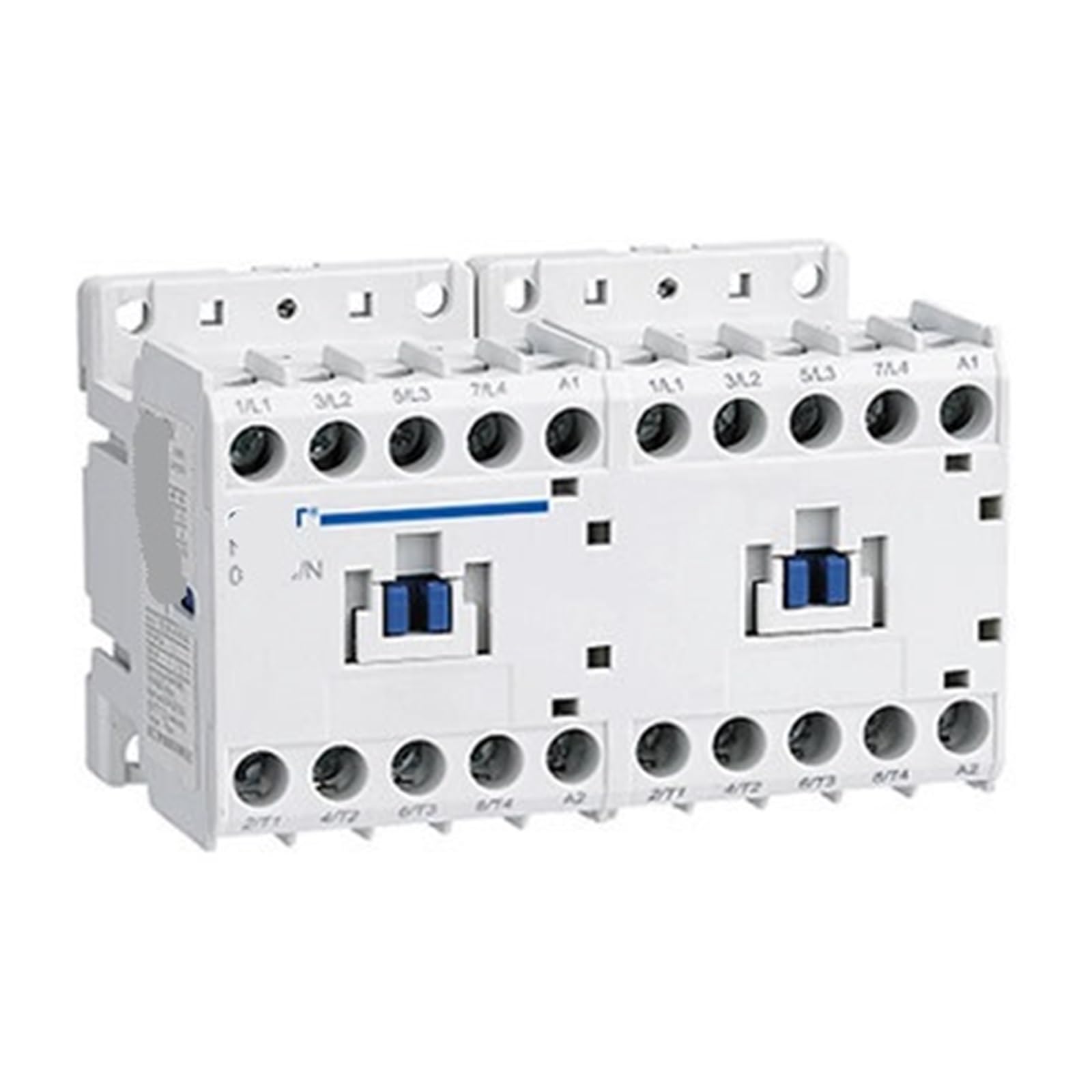
An image showing the XCGQFICOM NC8 Series Reversible AC Contactor, highlighting its compact design and terminal layout.
4. Specifications
| Feature | Specification |
|---|---|
| Model | NC8-12/N/22 |
| Control Voltage | DC110V |
| Type | Reversible AC Contactor |
| Manufacturer | XCGQFICOM |
| Package Dimensions | 1.18 x 0.79 x 0.39 inches |
| Item Weight | 1.76 ounces |
| Assembly Required | No |
| Number of Pieces | 1 |
5. Setup and Installation
Follow these steps for proper installation:
- Mounting: Securely mount the contactor on a DIN rail or panel using appropriate fasteners. Ensure adequate ventilation around the unit.
- Power Disconnection: Before making any electrical connections, ensure that all power to the circuit is disconnected at the main breaker.
- Wiring: Connect the main power supply to the L1, L2, L3 terminals and the motor leads to the T1, T2, T3 terminals. Connect the DC110V control voltage to the A1 and A2 coil terminals for each contactor as per the wiring diagram.
- Control Circuit: Wire the control circuit (e.g., push buttons, limit switches) to activate the respective contactor coils. Ensure proper interlocking to prevent both contactors from being energized simultaneously.
- Grounding: Ensure the contactor and motor are properly grounded according to local electrical codes.
- Verification: Double-check all wiring connections for tightness and correctness before restoring power.
6. Wiring Diagram
A detailed wiring diagram is crucial for correct installation. Due to variations in specific application requirements, a generic diagram is not provided here. Always refer to the specific wiring diagram provided with your motor and control system, or consult a qualified electrician for proper integration. The NC8 series typically features clearly labeled terminals for power input, motor output, and control coil connections (A1/A2).
7. Operating Instructions
Once installed and wired correctly, the reversible AC contactor operates as follows:
- Power On: Restore power to the main circuit.
- Forward Operation: Activate the control circuit for the 'forward' contactor. The contactor coil will energize, closing the main contacts and supplying power to the motor in the forward direction.
- Stop: Deactivate the 'forward' control circuit. The contactor coil will de-energize, opening the main contacts and stopping the motor.
- Reverse Operation: After the motor has come to a complete stop (or nearly stopped, depending on application requirements), activate the control circuit for the 'reverse' contactor. The contactor coil will energize, closing its main contacts and supplying power to the motor in the reverse direction.
- Interlocking: The built-in mechanical and electrical interlocks prevent both forward and reverse contactors from being energized simultaneously, protecting the motor and power supply.
8. Maintenance
Regular maintenance ensures the longevity and reliable operation of your contactor:
- Visual Inspection: Periodically inspect the contactor for signs of wear, damage, or overheating (discoloration). Check for loose connections.
- Cleaning: Keep the contactor free from dust, dirt, and moisture. Use a dry, soft cloth for cleaning. Do not use solvents.
- Contact Inspection: If accessible and safe to do so (with power disconnected), inspect the main contacts for excessive pitting or erosion. Replace the contactor if contacts are severely worn.
- Terminal Tightness: Re-tighten terminal screws periodically, especially in environments with vibration.
- Environmental Conditions: Ensure the operating environment remains within the specified temperature and humidity ranges.
9. Troubleshooting
Refer to the table below for common issues and their potential solutions:
| Problem | Possible Cause | Solution |
|---|---|---|
| Contactor does not energize | No control voltage; Open control circuit; Faulty coil | Check control voltage supply; Inspect control wiring and switches; Test coil resistance (replace if open) |
| Motor does not start | No main power; Overload tripped; Faulty motor; Contactor contacts not closing | Check main power supply; Reset overload relay; Inspect motor; Check contactor for mechanical issues or wear |
| Contactor hums loudly | Loose laminations; Dirt in magnet gap; Incorrect voltage | Tighten screws; Clean magnet faces; Verify correct control voltage |
| Contactor overheats | Overload; Poor ventilation; Loose connections | Reduce load; Improve ventilation; Tighten all connections |
| Both contactors try to energize | Interlock failure; Wiring error | Inspect mechanical and electrical interlocks; Verify control circuit wiring |
If troubleshooting steps do not resolve the issue, contact a qualified electrician or the manufacturer for assistance.
10. Warranty and Support
XCGQFICOM products are manufactured to high-quality standards. For specific warranty terms and conditions, please refer to the documentation provided at the time of purchase or contact your supplier. For technical support or inquiries, please reach out to XCGQFICOM customer service through their official channels.


