1. Introduction
This manual provides essential information for the safe and effective installation, operation, and maintenance of the Generic 6-Inch Wafer Butterfly Valve, Model BFVM1025. This valve is designed for industrial and scientific applications requiring reliable flow control. Please read this manual thoroughly before installation or operation.
2. Safety Information
Adherence to the following safety guidelines is crucial for preventing injury and equipment damage.
- Always wear appropriate personal protective equipment (PPE) during installation, maintenance, and operation.
- Ensure the system is depressurized and drained before attempting any installation or maintenance.
- Verify that the valve's pressure rating (200 PSI) is suitable for the application's maximum operating pressure.
- Do not modify the valve. Unauthorized modifications can compromise safety and performance.
- Handle the valve with care to avoid damage to the body, disc, or seals.
3. Product Overview
The Generic 6-Inch Wafer Butterfly Valve is constructed with a ductile iron body and features a nickel-plated disc and Buna seats. It is equipped with a 10-position handle for precise flow control.

Figure 1: Front view of the 6-inch Wafer Butterfly Valve, showing the red ductile iron body, black disc, and operating handle.
This valve is suitable for various applications, including agriculture, oil & gas, and tank truck systems, offering robust performance with its 410 stainless steel stem and greasable stem design.

Figure 2: Diagram highlighting the multi-use capabilities and key features such as 410 Stainless Stem, 200 PSI rating, and greasable stem.
4. Setup and Installation
Proper installation is critical for the valve's performance and longevity. Refer to the detailed diagrams for dimensions and component identification.

Figure 3: Technical drawing of the DWBV Series Wafer Butterfly Valve, showing detailed dimensions, parts list, and flange specifications (ISO 5752, ISO 5211, ANSI 150).
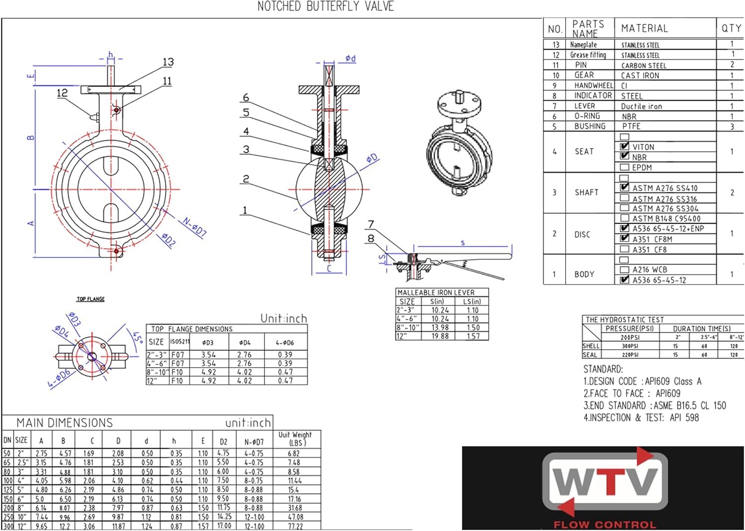
Figure 4: Engineering drawing of a notched butterfly valve, providing main dimensions, material specifications for various parts, and pressure test information.
- Preparation: Ensure the pipeline is clean and free of debris. Verify that the mating flanges are clean, flat, and properly aligned.
- Gasket Placement: The valve's integral seats act as gaskets. No additional flange gaskets are typically required.
- Valve Positioning: Center the valve between the flanges. Ensure the disc is in the partially open position (approximately 10-20 degrees) to prevent damage during installation.
- Bolt Installation: Insert flange bolts through the pipeline flanges and the valve body. Hand-tighten all bolts.
- Tightening Sequence: Gradually tighten the bolts in a crisscross pattern to ensure even compression and prevent flange distortion. Refer to ANSI 150 flange specifications for appropriate torque values.
- Final Check: After tightening, cycle the valve through its full range of motion (open to close) to ensure smooth operation and proper seating.
5. Operating Instructions
The butterfly valve is operated using a 10-position handle, allowing for incremental flow adjustment.

Figure 5: Close-up of the 10-position handle mechanism, showing the notched plate for precise disc positioning and the 'CLOSE' and 'OPEN' indicators.
- Opening the Valve: Move the handle towards the 'OPEN' indicator. Each notch corresponds to a specific disc position, allowing for throttling.
- Closing the Valve: Move the handle towards the 'CLOSE' indicator until it reaches the fully closed position.
- Throttling: The 10-position handle allows for intermediate settings to regulate flow. Avoid prolonged operation in partially open positions if cavitation or excessive wear is a concern for the specific application.
6. Maintenance
Regular maintenance ensures optimal performance and extends the lifespan of the valve.
- Inspection: Periodically inspect the valve for external leaks, corrosion, or damage to the body, handle, and stem.
- Lubrication: The valve features a greasable stem. Apply appropriate grease to the stem lubrication point as needed to ensure smooth operation and prevent wear.
- Seat Condition: Monitor the condition of the Buna seats. If signs of wear or leakage are observed, the valve may require servicing or replacement.
- Actuator Check: Ensure the 10-position handle mechanism operates freely and securely locks into each position.
- Cleaning: Keep the exterior of the valve clean to prevent accumulation of corrosive substances.
7. Troubleshooting
This section addresses common issues that may arise during the valve's operation.
| Problem | Possible Cause | Solution |
|---|---|---|
| Leakage at flange connection | Improper bolt tightening, damaged seat, misaligned flanges | Retighten bolts in crisscross pattern; inspect seat for damage; verify flange alignment. |
| Valve difficult to operate | Lack of lubrication, stem corrosion, debris in seat area | Lubricate stem; clean stem and seat area; inspect for internal damage. |
| Valve not fully closing/opening | Obstruction, damaged disc, handle mechanism issue | Inspect for obstructions; check disc for damage; examine handle and stem connection. |
8. Specifications
Detailed technical specifications for the Generic 6-Inch Wafer Butterfly Valve.
| Feature | Specification |
|---|---|
| Model Number | BFVM1025 |
| Size | 6 Inch |
| Body Material | Ductile Iron |
| Disc Material | Nickel Plated DI |
| Seat Material | Buna |
| Stem Material | 410 Stainless Steel (Square Stem) |
| Maximum Operating Pressure | 200 PSI |
| Handle Type | 10 Position Handle |
| Face To Face Standard | ISO 5752 |
| Mounting Pad Standard | ISO 5211 |
| Flange Standard | ANSI 150 |
| Number of Ports | 2 |
| Item Weight | 18 pounds |
| Product Dimensions (L x W x H) | 14 x 9 x 5 inches |
9. Warranty and Support
For warranty information or technical support, please contact the seller or manufacturer directly. Keep your purchase receipt and product model number (BFVM1025) available for reference.