1. Introduction and Overview
The eletechsup R4IOJ32 is a versatile 32-channel RS485 multi-function IO core board designed for Modbus RTU input/output control. This compact board can be easily integrated into various function boards and systems, serving as a PLC HMI remote IO expansion solution. It supports multiple input/output configurations and offers flexible power supply options.
This manual provides detailed instructions for the 16DI-16DO With Pin variant, covering its features, setup, operation, and configuration.
2. Product Features
- Power Supply Options: DC 6-26V (with anti-reverse protection) or DC 4-5.5V (reverse connection prohibited).
- Low Working Current: Operates at 9mA.
- MODBUS RTU Support: Compatible with function codes Write 05/06/15/16 and Read 01/02/03.
- Configurable IO Modes: Five selectable modes via jumper: 32DI, 32DO, 16DI-16DO, 8DI-24DO, 24DI-8DO.
- Adjustable Input/Output Levels: NPN/PNP levels can be switched by modifying registers 0X00F5/0X00F6.
- Communication Anomaly Handling: Configurable restart (0X00F3) and output shutdown (0X00F4) on communication failure.
- Input Mode Flexibility: Supports 3.3V/5V TTL level input, with options for low level (default) and high level input.
- Output Mode: 5V TTL level, configurable for low level (default) or high level output.
- Scalable MODBUS: Supports up to 247 devices in parallel in MODBUS command mode.
- Input Status: Supports query (default) and automatic reporting.
- Configurable Baud Rates: 1200, 2400, 4800, 9600 (default), 19200, 38400, 57600, 115200, with None/Odd/Even Parity options.
- Compact Interface: 2.54MM pin header for easy connection with Dupont wires or breadboards.
- Small Form Factor: Dimensions of 51mm x 34mm x 4mm and a weight of 8 grams.
3. Specifications
| Parameter | Value |
|---|---|
| Brand | eletechsup |
| Model | R4IOJ32 (16DI-16DO With Pin) |
| Power Supply 1 | DC 6-26V (with anti-reverse protection) |
| Power Supply 2 | DC 4-5.5V (reverse connection prohibited) |
| Working Current | 9mA |
| MODBUS RTU Function Codes | Write 05/06/15/16, Read 01/02/03 |
| IO Modes | 32DI, 32DO, 16DI-16DO, 8DI-24DO, 24DI-8DO (selectable) |
| Input Level Support | 3.3V/5V TTL (Low/High level) |
| Output Level | 5V TTL (Low/High level) |
| Max MODBUS Devices | 247 (in parallel) |
| Baud Rates | 1200, 2400, 4800, 9600 (default), 19200, 38400, 57600, 115200 |
| Parity | None/Odd/Even |
| Interface | 2.54MM Pin Header |
| Dimensions | 51mm x 34mm x 4mm |
| Weight | 8 grams |
| UPC | 765057027362 |
4. Setup and Installation
4.1 Board Variants
The R4IOJ32 board is available in two main variants: "Only Board" and "With Pin". The "With Pin" version, which is the subject of this manual, includes pre-soldered 2.54mm pin headers for easier integration and connection.

Figure 4.1: R4IOJ32 Board Variants (Only Board vs. With Pin)
4.2 Power Supply Connection
The R4IOJ32 board offers two power supply options. Only one power supply should be used at a time.
- Power Supply 1 (DC 6-26V): Connect to the B+ and A- terminals. This input includes anti-reverse protection.
- Power Supply 2 (DC 4-5.5V): Connect to the 5V and GND terminals. Reverse connection is prohibited for this input.
4.3 RS485 Communication Port
Connect your RS485 communication lines to the designated RS485 Port terminals on the board.
4.4 IO Port Connections
The IO ports are accessible via the 2.54mm pin headers. Refer to the specific IO mode configuration section for detailed pin assignments.

Figure 4.2: R4IOJ32 Power, RS485, and IO Port Overview
Tip: The pin header spacing is 2.54mm, suitable for standard Dupont wires or breadboard connections.
5. Operating Instructions
5.1 MODBUS RTU Communication
The R4IOJ32 operates using the MODBUS RTU protocol. It supports standard function codes for writing (05, 06, 15, 16) and reading (01, 02, 03) data. In MODBUS command mode, the board can be part of a network with up to 247 devices in parallel.
5.2 Baud Rate and Parity Settings
The communication baud rate can be configured to 1200, 2400, 4800, 9600 (default), 19200, 38400, 57600, or 115200. Parity options include None, Odd, or Even. These settings are typically configured via software commands to the board.
5.3 Input Port Status
The status of the input ports can be queried (default behavior) or configured for automatic reporting, depending on your application requirements.
5.4 Communication Anomaly Handling
- Restart on Anomaly: By setting the 0X00F3 register, the board can be configured to restart automatically if communication becomes abnormal.
- Close Outputs on Anomaly: By setting the 0X00F4 register, all output ports can be configured to close automatically if communication becomes abnormal. This provides a safety mechanism for connected devices.
6. IO Modes Configuration
The R4IOJ32 is a multi-function board allowing selection of five different IO modes. These modes are configured using jumpers (0603 0Ω resistor or wire) on the board.
6.1 Jumper Settings for IO Modes
The board features M1, M2, M3, and M4 jumper pads. By soldering or wiring these pads in specific configurations, you can select the desired IO mode:

Figure 6.1: Jumper Configuration Table for IO Modes
The image below illustrates the location of the mode selection jumpers on the board:
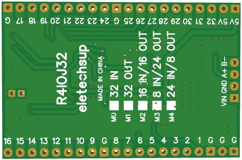
Figure 6.2: Location of Mode Selection Jumpers
6.2 Pinout Diagrams for Each IO Mode
The following diagrams illustrate the pin assignments for each of the available IO modes:

Figure 6.3: Pinout Diagrams for All IO Modes
For the 16DI-16DO configuration, which is the specific model covered by this manual, the pinout is as follows:
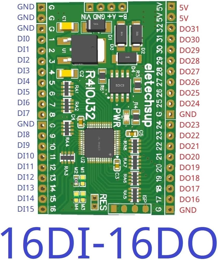
Figure 6.4: 16DI-16DO Pinout Diagram
7. Input and Output Level Configuration
The R4IOJ32 allows for flexible configuration of input and output levels (NPN/PNP) by modifying specific registers.
7.1 Switching Input/Output Levels
- Input Level (NPN/PNP): Modify register 0X00F5 to switch between NPN and PNP input types.
- Output Level (NPN/PNP): Modify register 0X00F6 to switch between NPN and PNP output types.
The default configuration is NPN Input & NPN Output (Register 0X00F5=0, 0X00F6=0).

Figure 7.1: Input and Output Level Configurations
8. Troubleshooting
8.1 Factory Reset
If you encounter issues or wish to revert to default settings, you can perform a factory reset. Short the RES jumper on the board for 5 seconds to restore the factory settings.
Figure 8.1: Location of RES Jumper for Factory Reset
8.2 General Troubleshooting Tips
- Ensure correct power supply voltage and polarity.
- Verify RS485 wiring for correct A/B connections.
- Check jumper settings for the desired IO mode.
- Confirm Modbus communication parameters (baud rate, parity, address).
- Refer to the Modbus RTU protocol documentation for detailed command structures.
9. Maintenance
The R4IOJ32 board is designed for reliable operation with minimal maintenance. To ensure longevity and proper function:
- Keep the board clean and free from dust and debris.
- Avoid exposing the board to extreme temperatures or humidity.
- Ensure proper ventilation if enclosed in a case.
- Handle with care to prevent physical damage to components or pins.
10. What's in the Box
The package for the "16DI-16DO With Pin" variant typically includes:
- One R4IOJ32 Core Board (16DI-16DO With Pin)
11. Warranty and Support
For warranty information, technical support, or if you require more detailed documentation, please contact the manufacturer, eletechsup, directly through their official channels or the platform where the product was purchased.