1. Introduction
Thank you for choosing the AstroAI AM33D or DM200M Digital Multimeter. This manual provides essential information for the safe and effective operation, maintenance, and troubleshooting of your device. Please read this manual thoroughly before use and retain it for future reference.
1.1 Safety Information
Always adhere to basic safety precautions when using electrical testing equipment to reduce the risk of fire, electric shock, or personal injury. This device is designed for safe operation when used according to these instructions.
- Read all instructions: Understand the functions and limitations of the multimeter before operation.
- Use appropriate range: Always select the correct measurement range to avoid damage to the meter or the circuit being tested.
- Inspect test leads: Before each use, check test leads for damaged insulation or exposed metal. Replace if damaged.
- Do not exceed maximum input values: Refer to the specifications section for maximum voltage and current ratings.
- Avoid wet conditions: Do not operate the multimeter in wet environments.
- Ensure proper fuse protection: The multimeters are equipped with ceramic fuses to protect against burning and overloading. Do not bypass or use incorrect fuses.
- Disconnect power: Always disconnect power to the circuit before connecting or disconnecting test leads, especially when measuring current.
- Beware of live circuits: Exercise extreme caution when working with live circuits.
2. Product Overview and Features
The AstroAI AM33D and DM200M are versatile digital multimeters designed for accurate measurement of various electrical parameters. They are suitable for household, automotive, and general electrical troubleshooting.

Figure 2.1: AstroAI DM200M Digital Multimeter with included test leads and a 9V battery. This image displays the main unit, red and black test probes, and a standard 9V battery, illustrating the complete package.
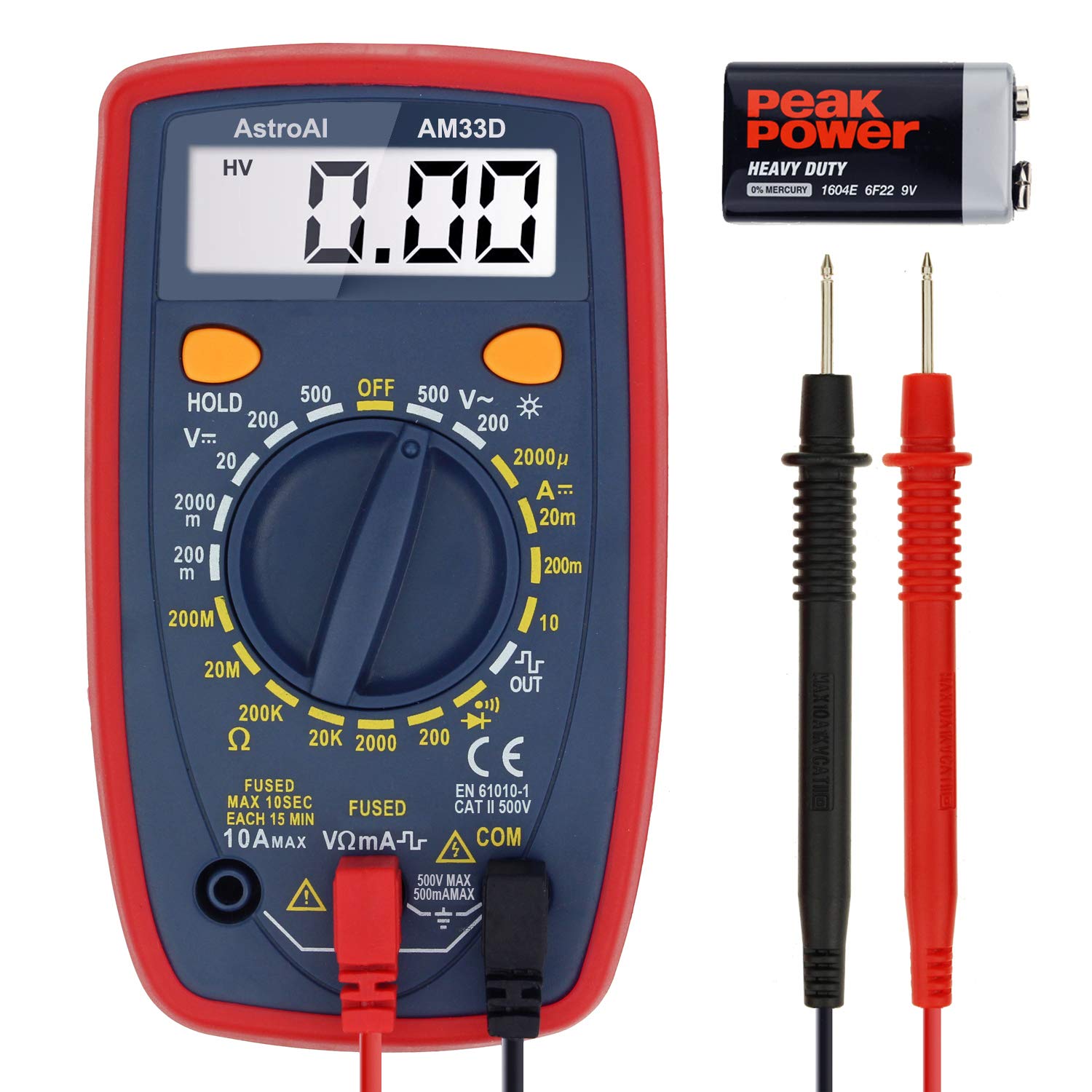
Figure 2.2: AstroAI AM33D Digital Multimeter with included test leads and a 9V battery. This image shows the AM33D model, its test probes, and a 9V battery, highlighting the components.
2.1 Key Features
- Versatile Measurements: Accurately measures AC/DC Voltage, DC Current, Resistance, and Diode. The DM200M also includes Non-Contact Voltage (NCV) detection.
- User-Friendly Design: Features data hold, max value recording, 15-minute auto power off, and a low battery indicator.
- Enhanced Readability: Backlit display and flashlight (DM200M) for easy troubleshooting in dimly lit areas.
- Portable and Compact: Designed for easy transport and storage, fitting into toolboxes or glove compartments.
- Safety Features: Equipped with two ceramic fuses to protect against burning and overloading. Includes a silicone protective case and a kickstand for convenience.
3. Setup
3.1 Battery Installation
The multimeters typically use a 9V battery. To install or replace the battery:
- Ensure the multimeter is turned OFF and disconnect all test leads.
- Locate the battery compartment cover on the back of the unit.
- Unscrew the retaining screw(s) and remove the cover.
- Insert a new 9V battery, observing the correct polarity (+ and -).
- Replace the battery compartment cover and secure it with the screw(s).
3.2 Connecting Test Leads
Always connect the test leads correctly for accurate and safe measurements.
- Insert the black test lead into the COM (common) jack.
- For most voltage, resistance, and diode measurements, insert the red test lead into the VΩmA jack.
- For current measurements (up to 10A), insert the red test lead into the 10A jack.
- For smaller current measurements (up to 200mA/250mA), insert the red test lead into the VΩmA jack.
4. Operating Instructions
This section details how to perform various measurements using your AstroAI digital multimeter.
4.1 General Operation
- Rotary Switch: Turn the rotary switch to the desired measurement function and range.
- HOLD Button: Press to freeze the current reading on the display. Press again to release.
- MAX Button (DM200M): Press to display the maximum measured value. Press again to exit.
- FUNC Button (DM200M): Used to switch between different functions within a single rotary switch position (e.g., AC/DC, Diode/Continuity).
- Backlight Button (DM200M): Press to turn on the display backlight. Press again to turn off.
4.2 AC Voltage Measurement
To measure AC voltage:
- Set the rotary switch to the 'V~' (AC Voltage) range. Select an appropriate range higher than the expected voltage.
- Connect the test leads to the circuit in parallel with the load.
- Read the voltage value on the display.

Figure 4.1: The AM33D multimeter measuring AC voltage from a standard wall outlet. The display shows '110', indicating 110V AC. Note: The meter cannot be used to test AC current when the dial is set to AC voltage.
4.3 DC Voltage Measurement
To measure DC voltage:
- Set the rotary switch to the 'V--' (DC Voltage) range. Select an appropriate range higher than the expected voltage.
- Connect the red test lead to the positive (+) side of the circuit and the black test lead to the negative (-) side.
- Read the voltage value on the display.

Figure 4.2: The AM33D multimeter measuring DC voltage from a 9V battery. The display shows '9.69', indicating 9.69V DC.

Figure 4.3: The DM200M multimeter measuring DC voltage from a 9V battery. This image demonstrates the DM200M's capability for DC voltage measurement.
4.4 DC Current Measurement
To measure DC current:
- IMPORTANT: Disconnect power to the circuit before connecting the multimeter.
- Set the rotary switch to the 'A--' (DC Current) range. Select an appropriate range.
- Connect the multimeter in series with the circuit. For currents up to 10A, use the 10A jack for the red lead. For smaller currents, use the VΩmA jack.
- Apply power to the circuit and read the current value on the display.

Figure 4.4: The DM200M multimeter measuring DC current in a car battery circuit. The display shows '0.68', indicating 0.68A DC. This illustrates how to measure current in series.
4.5 Resistance Measurement
To measure resistance:
- Ensure the circuit is completely de-energized before measuring resistance.
- Set the rotary switch to the 'Ω' (Resistance) range.
- Connect the test leads across the component whose resistance you wish to measure.
- Read the resistance value on the display.
4.6 Diode Test and Continuity Test
To perform a diode test or continuity test:
- Ensure the circuit is de-energized.
- Set the rotary switch to the Diode/Continuity symbol. Use the FUNC button on DM200M to toggle between functions if needed.
- For Diode Test: Connect the red lead to the anode and the black lead to the cathode. The display will show the forward voltage drop. Reverse the leads to check for open circuit.
- For Continuity Test: Connect the test leads across the component. A low resistance (typically below 50Ω) will indicate continuity, often accompanied by an audible beep.
4.7 Non-Contact Voltage (NCV) Detection (DM200M Only)
The DM200M model features NCV detection for identifying live AC voltage without direct contact.
- Set the rotary switch to the 'NCV' position.
- Move the top end of the multimeter near the conductor or outlet.
- The multimeter will emit an audible beep and/or flash an indicator light if AC voltage is detected.

Figure 4.5: The DM200M multimeter being used for versatile circuit troubleshooting in an engine bay. The image highlights various functions like AC/DC Voltage, Resistance, NCV, Data Hold, and Max Value, demonstrating its broad application.
4.8 Backlit Display (DM200M Only)
The DM200M features an easy-to-read backlit display for use in low-light conditions.

Figure 4.6: The DM200M multimeter displaying a clear, backlit reading. The image also provides an internal view, illustrating the placement of the 250mA and 10A ceramic fuses for enhanced safety.
5. Maintenance
5.1 Fuse Replacement
The multimeters are protected by internal ceramic fuses. If the current measurement function stops working, the fuse may need replacement.
- Ensure the multimeter is turned OFF and disconnect all test leads.
- Open the battery compartment cover (refer to Section 3.1).
- Carefully remove the back casing of the multimeter to access the circuit board and fuses.
- Identify the blown fuse(s). The DM200M typically has a 250mA/250V fuse and a 10A/250V fuse. The AM33D has a 500mA/500V and a 10A/500V fuse.
- Replace the blown fuse(s) with new fuses of the exact same type and rating. Using incorrect fuses can compromise safety and damage the meter.
- Reassemble the multimeter, ensuring all screws are securely fastened.
5.2 Cleaning
To clean the multimeter, wipe the case with a damp cloth and a mild detergent. Do not use abrasives or solvents. Ensure the device is completely dry before use.
6. Troubleshooting
- No display or dim display: Check the battery. Replace if low.
- Incorrect readings: Ensure test leads are properly connected, the correct function/range is selected, and the circuit is de-energized for resistance/continuity tests.
- Current measurement not working: Check and replace the appropriate fuse (refer to Section 5.1).
- Low battery indicator: A battery symbol on the display indicates that the battery voltage is low and needs replacement.
7. Specifications
| Parameter | Value |
|---|---|
| Brand | AstroAI |
| Model Numbers | AM33D, DM200M |
| Display Counts | 2000 Counts |
| Measurement Type | Multimeter (AC/DC Voltage, DC Current, Resistance, Diode) |
| Additional Functions (DM200M) | NCV, Backlight, Max Value Recording |
| Power Source | Battery Powered (9V battery, typically) |
| Safety Rating (DM200M) | CAT III 600V |
| Safety Rating (AM33D) | CAT II 500V |
| Auto Power Off | 15 minutes (approx.) |
| Fuses (DM200M) | 250mA/250V, 10A/250V Ceramic Fuses |
| Fuses (AM33D) | 500mA/500V, 10A/500V Ceramic Fuses |
8. Warranty and Support
AstroAI provides a limited warranty for its products. For specific warranty details, claims, or technical support, please refer to the warranty card included with your product or visit the official AstroAI website. Do not attempt to repair the device yourself, as this may void the warranty and pose safety risks.