1. Introduction
This manual provides essential information for the safe and efficient operation, installation, and maintenance of the UOFKIPBA VFD-M Series Inverter. This series includes models VFD007M43A, VFD015M43A, and VFD015M43B, designed for various industrial applications requiring precise motor speed control. Please read this manual thoroughly before installation or operation to ensure proper usage and prevent potential hazards.
2. Safety Information
WARNING: Improper installation or operation may result in serious injury or equipment damage. Always follow safety guidelines.
- Electrical Hazard: Ensure power is disconnected before performing any wiring or maintenance. Wait for the capacitor discharge indicator to extinguish before touching terminals.
- Qualified Personnel: Installation, wiring, and maintenance should only be performed by qualified electrical personnel.
- Grounding: Always ensure the inverter is properly grounded according to local and national electrical codes.
- Environment: Do not install the inverter in environments with excessive dust, corrosive gases, high humidity, or direct sunlight.
- Emergency Stop: Ensure an external emergency stop circuit is in place and functional.
3. Product Overview
The UOFKIPBA VFD-M Series Inverter is a compact and versatile variable frequency drive designed for controlling the speed of AC motors. It features a user-friendly control panel for easy parameter setting and monitoring.

Figure 3.1: Front and side view of the UOFKIPBA VFD-M Series Inverter. This image displays the main unit, highlighting its compact design and the integrated control panel with a digital display and operational buttons.

Figure 3.2: Detailed view of the inverter's control panel. The image shows the digital display, 'RUN' and 'STOP' buttons, navigation keys, and a rotary dial for parameter adjustment, all essential for user interaction.
Key Features:
- Variable frequency output for precise motor speed control.
- Integrated control panel with digital display.
- Multiple protection functions (overcurrent, overvoltage, undervoltage, overload, etc.).
- Compact design for space-saving installation.
4. Setup and Installation
Proper installation is critical for the inverter's performance and longevity. Ensure all local and national electrical codes are followed.
4.1 Mounting
Mount the inverter vertically on a flat, non-flammable surface. Ensure adequate clearance around the unit for proper ventilation and heat dissipation. Avoid mounting in direct sunlight or near heat sources.
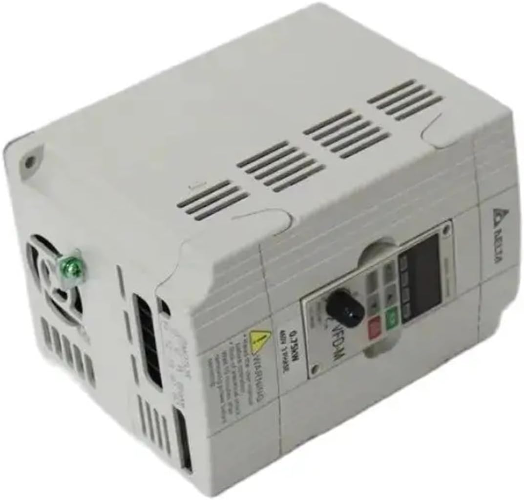
Figure 4.1: Top-down view of the inverter, illustrating the ventilation grilles. This perspective is useful for understanding airflow requirements and ensuring proper heat dissipation during installation.
4.2 Wiring
All wiring must be performed by a qualified electrician. Refer to the wiring diagram provided with your specific model for detailed connections. Ensure correct input power (380V, 3-phase) and motor connections.
- Power Input (R, S, T): Connect the 380V AC three-phase power supply.
- Motor Output (U, V, W): Connect to the motor terminals.
- Ground (PE): Connect to a reliable ground point.
- Control Terminals: Connect external control signals (e.g., start/stop, speed reference) as required by your application.
CAUTION: Do not connect the main power supply to the output terminals (U, V, W). This will damage the inverter.
5. Operating Instructions
After successful installation and wiring, the inverter is ready for operation.
5.1 Initial Power-Up
- Verify all wiring connections are secure and correct.
- Apply main power to the inverter. The digital display should illuminate.
- Observe the display for any error codes. If an error occurs, refer to the Troubleshooting section.
5.2 Basic Operation
- Start: Press the RUN button on the control panel to start the motor.
- Stop: Press the STOP button to stop the motor.
- Speed Adjustment: Use the rotary dial or the UP/DOWN arrow keys on the control panel to adjust the output frequency, thereby changing the motor speed.
- Parameter Setting: Access the parameter menu using the 'MODE' or 'PRG' button. Navigate through parameters and adjust values using the arrow keys and rotary dial. Refer to the detailed parameter list in the full product manual for specific settings.
6. Maintenance
Regular maintenance ensures optimal performance and extends the lifespan of your inverter.
- Cleaning: Periodically clean the inverter's exterior and ventilation openings to prevent dust accumulation. Use a soft, dry cloth. Do not use liquid cleaners.
- Inspection: Regularly inspect wiring connections for tightness and signs of wear or damage. Check for any unusual noises or odors during operation.
- Environmental Check: Ensure the operating environment remains within specified temperature and humidity ranges.
- Fan Replacement: Cooling fans have a limited lifespan. Consider periodic replacement based on operating hours and environmental conditions.
WARNING: Always disconnect power and wait for capacitor discharge before performing any maintenance.
7. Troubleshooting
This section provides solutions for common issues encountered during inverter operation.
| Problem | Possible Cause | Solution |
|---|---|---|
| Inverter does not power on | No input power; Blown fuse; Incorrect wiring | Check power supply; Replace fuse; Verify wiring connections. |
| Motor does not run | Emergency stop active; Incorrect motor wiring; Parameter settings incorrect | Check E-stop circuit; Verify motor wiring (U, V, W); Review motor parameters. |
| Overcurrent fault (OC) | Motor overload; Short circuit in motor/cables; Acceleration time too short | Reduce load; Check motor/cables; Increase acceleration time parameter. |
| Overvoltage fault (OV) | Input voltage too high; Deceleration time too short; Regenerative load | Check input voltage; Increase deceleration time; Consider braking resistor. |
For other error codes or persistent issues, consult the comprehensive troubleshooting guide in the full product manual or contact technical support.
8. Specifications
The following specifications apply to the UOFKIPBA VFD-M Series Inverters, including models VFD007M43A, VFD015M43A, and VFD015M43B.

Figure 8.1: Bottom view of the inverter, showing mounting points and product labels. This view provides details on model numbers, electrical ratings, and certifications, crucial for technical reference.
- Input Voltage: 380V AC, 3-Phase
- Output Voltage: 0 to 380V AC, 3-Phase
- Output Frequency: 0.1 to 400 Hz
- Power Ratings:
- VFD007M43A: 0.75KW
- VFD015M43A: 1.5KW
- VFD015M43B: 1.5KW
- Control Method: V/F control, Sensorless Vector Control
- Protection Functions: Overcurrent, Overvoltage, Undervoltage, Overload, Overheat, etc.
- Operating Temperature: -10°C to 50°C (14°F to 122°F)
- Humidity: Less than 90% RH (non-condensing)
- Dimensions (Approximate): 1.18 x 0.79 x 0.39 inches (Package Dimensions)
- Item Weight (Approximate): 1.76 ounces
9. Warranty and Support
For warranty information, technical support, or service inquiries, please contact your authorized UOFKIPBA distributor or the manufacturer directly. Ensure you have your product model number and purchase date available when contacting support.

Figure 9.1: The UOFKIPBA VFD-M Series Inverter alongside its original packaging box. This image is relevant for identifying product details on the box for warranty claims or returns.