1. Introduction and Overview
This manual provides detailed instructions for the installation, operation, and maintenance of the Huayong DM856 Microstep Motor Driver. The DM856 is a fully digital 2-phase stepping driver designed for use with 2-phase hybrid stepper motors, particularly those with 57mm and 60mm outside diameters. It features advanced ARM control for smooth, quiet, and vibration-free motor operation.
Key Features:
- Anti-Resonance: Provides optimal torque, extra smooth motion, and reduced motor heating and noise.
- Signal Input: Features strong anti-interference capability for reliable signal processing.
- Safety and Reliability: Includes overheat, overcurrent, undervoltage lockout, and input voltage protection against reversal. The current is automatically halved at standstill to reduce heat.
- Versatile Application: Suitable for various small and medium-sized automation equipment and instruments, such as engraving machines, marking machines, cutting machines, illumination systems, plotters, and CNC machine tools.

Figure 1: Huayong DM856 Microstep Motor Driver showing front, side, top, and bottom views.
2. Setup and Installation
2.1 Wiring Connections
Ensure all power is disconnected before making any wiring connections. Connect the motor driver to the stepper motor and power supply according to the diagram below. Pay close attention to polarity for the power supply and motor phases.
- PUL+, PUL-: Pulse signal input.
- DIR+, DIR-: Direction signal input.
- ENA+, ENA-: Enable signal input.
- GND: Ground connection.
- VDC: DC power supply input (24V-80V DC).
- A+, A-, B+, B-: Motor phase connections.

Figure 2: Wiring diagram illustrating connections between the DM856 driver and a 2-phase stepper motor.
2.2 DIP Switch Settings
The DM856 driver features DIP switches for configuring the output current and microstep resolution. Refer to the tables and image below for proper configuration.
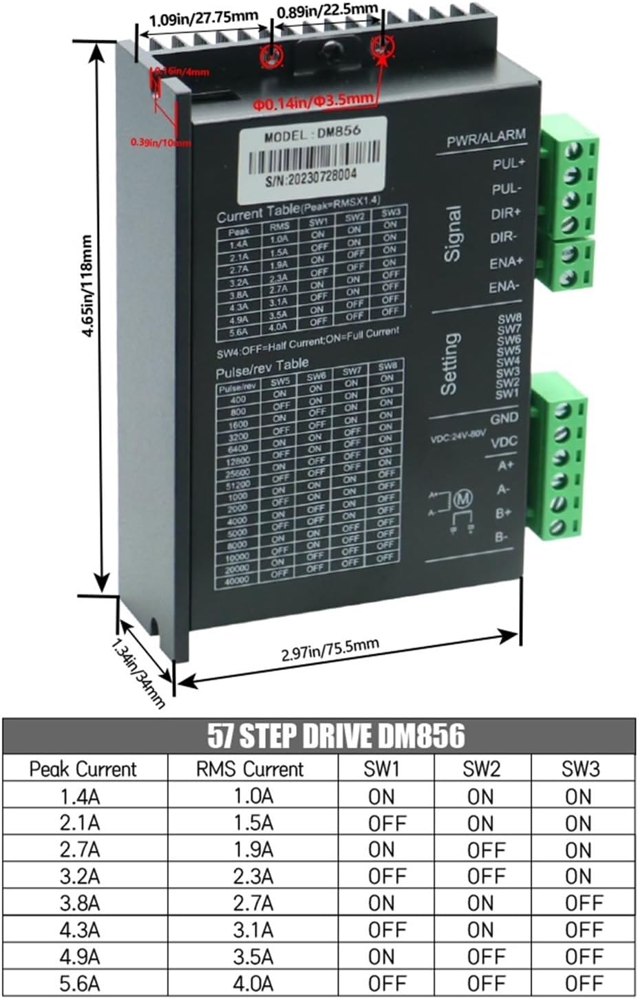
Figure 3: DM856 driver showing DIP switch settings for current and microstep resolution, along with dimensions.
2.2.1 Current Setting (SW1, SW2, SW3)
Use DIP switches SW1, SW2, and SW3 to set the desired peak output current for the motor. The current is adjustable in 8 channels from 1.4A/phase to 5.6A/phase.
| Peak Current | RMS Current | SW1 | SW2 | SW3 |
|---|---|---|---|---|
| 1.4A | 1.0A | ON | ON | ON |
| 2.1A | 1.5A | ON | ON | OFF |
| 2.7A | 1.9A | ON | OFF | ON |
| 3.2A | 2.3A | ON | OFF | OFF |
| 3.8A | 2.7A | OFF | ON | ON |
| 4.3A | 3.1A | OFF | ON | OFF |
| 4.9A | 3.5A | OFF | OFF | ON |
| 5.6A | 4.0A | OFF | OFF | OFF |
2.2.2 Microstep Setting (SW5, SW6, SW7, SW8)
Configure the microstep resolution using DIP switches SW5, SW6, SW7, and SW8. The driver supports 16 channels of constant angle, constant torque micro steps, with a highest micro step resolution of 51200 steps/rev.
| Pulse/rev | SW5 | SW6 | SW7 | SW8 |
|---|---|---|---|---|
| 400 | ON | ON | ON | ON |
| 800 | ON | ON | ON | OFF |
| 1600 | ON | ON | OFF | ON |
| 3200 | ON | ON | OFF | OFF |
| 6400 | ON | OFF | ON | ON |
| 12800 | ON | OFF | ON | OFF |
| 25600 | ON | OFF | OFF | ON |
| 51200 | ON | OFF | OFF | OFF |
| 1000 | OFF | ON | ON | ON |
| 2000 | OFF | ON | ON | OFF |
| 4000 | OFF | ON | OFF | ON |
| 5000 | OFF | ON | OFF | OFF |
| 10000 | OFF | OFF | ON | ON |
| 20000 | OFF | OFF | ON | OFF |
| 40000 | OFF | OFF | OFF | ON |
2.2.3 Half/Full Current Setting (SW4)
DIP switch SW4 controls the current reduction feature:
- SW4 OFF: Half Current (Current of winding will be reduced by approximately 50% when no step pulse command is received for 1.5 seconds).
- SW4 ON: Full Current (No current reduction at standstill).
3. Operating Instructions
Once the DM856 driver is correctly wired and configured, it is ready for operation. The driver interprets pulse and direction signals from a controller to precisely move the connected stepper motor.
- Pulse Input: The driver responds to pulse signals (PUL+, PUL-) to advance the motor by one microstep per pulse.
- Direction Input: The direction signal (DIR+, DIR-) determines the rotation direction of the motor.
- Enable Input: The enable signal (ENA+, ENA-) activates or deactivates the motor driver. When disabled, the motor windings are de-energized.
- Response Frequency: The DM856 supports a highest response frequency of 200KHz, allowing for high-speed motor control.
- Current Reduction: With SW4 set to OFF, the driver automatically reduces the motor winding current by approximately 50% after 1.5 seconds of inactivity. This feature helps to minimize motor heating and power consumption during idle periods.
4. Specifications
The following table details the technical specifications of the Huayong DM856 Microstep Motor Driver:
| Specification | Value |
|---|---|
| Model | DM856 |
| Supply Voltage | 24VDC to 80VDC |
| Drive Current | 1.4A to 5.6A/phase (adjustable in 8 channels) |
| Microstep Resolution | 16 channels, up to 51200 steps/rev |
| Response Frequency | Up to 200KHz |
| Signal I/O | Opto-isolated |
| Protections | Over-voltage, over-current, phase-error, undervoltage lockout, input voltage reversal |
| Item Weight | 10.6 ounces (300 Grams) |
| Package Dimensions | 1.18 x 0.79 x 0.39 inches |
| Manufacturer | Huayong |
5. Safety Information
Adhering to safety guidelines is crucial for preventing injury and damage to the equipment.
- Power Disconnection: Always ensure the power supply is disconnected before making any electrical connections, adjustments, or maintenance.
- Correct Polarity: Verify correct polarity for the DC power supply (24VDC to 80VDC) to prevent damage to the driver.
- Environmental Conditions: Avoid operating the driver in environments with excessive moisture, dust, corrosive gases, or extreme temperatures.
- Grounding: Proper grounding of the system is essential for safe operation and to minimize electrical noise.
- Ratings: Do not exceed the specified current and voltage ratings for the driver and connected motor.
- Professional Installation: If you are unfamiliar with electrical wiring or motor control, seek assistance from a qualified professional.
6. Maintenance
Regular maintenance helps ensure the longevity and reliable operation of your DM856 motor driver.
- Connection Inspection: Periodically inspect all wiring connections for tightness and signs of corrosion. Loose connections can lead to intermittent operation or damage.
- Cleanliness: Keep the driver clean and free from dust accumulation. Dust can impede heat dissipation and lead to overheating. Use a soft, dry cloth or compressed air for cleaning.
- Ventilation: Ensure adequate airflow and ventilation around the driver to prevent overheating, especially during continuous operation.
- Environmental Check: Monitor the operating environment to ensure it remains within the recommended temperature and humidity ranges.
7. Troubleshooting
This section provides solutions to common issues encountered with the DM856 motor driver.
- Motor Not Moving:
- Check if the power supply is connected and within the 24V-80V DC range.
- Verify all wiring connections (motor, power, control signals) are correct and secure.
- Ensure the pulse and direction signals are being sent correctly from the controller.
- Check if the enable signal (ENA) is active.
- Confirm that the current and microstep settings on the DIP switches are appropriate for your motor and application.
- Motor Vibrating Excessively or Making Noise:
- Adjust the microstep settings; higher microstep values generally result in smoother operation.
- Check for mechanical issues with the motor or load.
- Verify that the motor parameters (current, inductance) are compatible with the driver settings.
- Ensure the anti-resonance feature is functioning (inherent to the DM856 design).
- Driver Overheating:
- Ensure adequate ventilation around the driver.
- Verify that the motor current setting is not excessively high for the motor or application.
- Check for potential short circuits in the motor windings or wiring.
- If SW4 is ON (Full Current), consider setting it to OFF for automatic current reduction during idle periods.
- Motor Losing Steps:
- Increase the drive current setting if the motor is under heavy load.
- Reduce the acceleration and deceleration rates in your control program.
- Check for excessive mechanical load or friction in the system.
- Ensure the pulse frequency is not exceeding the motor's or driver's maximum response capability.