1. Introduction
This manual provides comprehensive instructions for the installation, operation, and maintenance of the WiXHC MK4-V 4-Axis USB Motion Control Card. This device is designed to serve as a high-performance CNC controller for Mach3 systems, supporting various applications including CNC engraving, and control of servo and stepper motors.
Please read this manual thoroughly before using the product to ensure safe and efficient operation. Keep this manual for future reference.
2. Safety Information
Always observe the following safety precautions to prevent injury and damage to the equipment:
- Ensure all power is disconnected before making any electrical connections or disconnections.
- Only qualified personnel should perform installation and maintenance.
- Verify correct wiring according to the provided diagrams to avoid short circuits or component damage.
- Operate the control card within its specified voltage and current limits.
- Keep the device away from moisture, dust, and extreme temperatures.
- Do not attempt to modify the hardware or firmware of the control card.
3. Package Contents
Upon opening the package, please verify that all items are present and undamaged:
- 1 x WiXHC MK4-V Motion Control Card
- 1 x USB Cable (3 meters)
- 1 x Wiring Diagram and Manual (digital access via QR code)
Note: A QR code is included in the package for accessing specific product manuals and driver files online.
4. Product Overview
4.1. Key Features
- Full support for all Mach3 versions.
- Data saving capability upon power loss.
- Spindle speed feedback and real-time display in Mach3.
- Maximum step-pulse frequency of 2000KHz.
- 16 general-purpose inputs and 8 general-purpose outputs.
- IO-port isolation for enhanced interference resistance and stable performance.
- USB 2.0 hot-swappable support.
- Status indicator LED for USB connection and working status.
- Aluminum alloy construction for durability and wear resistance.
4.2. External Dimensions
The following diagram illustrates the external dimensions of the MK4-V Motion Control Card.

Figure 4.2.1: External dimensions of the WiXHC MK4-V Motion Control Card. The diagram shows the top view of the board with measurements, indicating a length of approximately 103.69 mm and a width of 53.44 mm, with a height of 28.6 mm for the connectors.
4.3. Component Layout and Signal Description
Refer to the images below for a detailed view of the control card's components and signal descriptions.
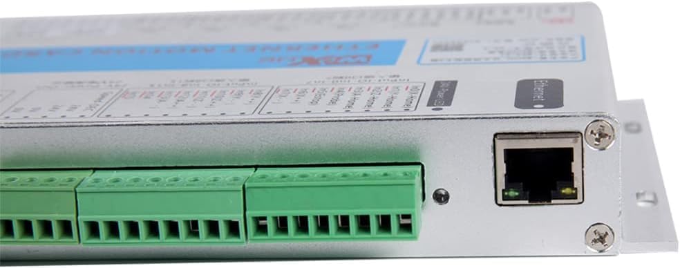
Figure 4.3.1: Close-up view of the WiXHC MK4-V Motion Control Card showing the USB port, Ethernet port, and various terminal blocks for input/output connections. The board is silver with green terminal blocks.

Figure 4.3.2: Signal description diagram for the WiXHC Motion Control Card. This image details the 16 input ports (Input #0 to Input #15), 8 output ports (OUT-1 to OUT-8), and spindle control connections, including 24V power input and output, and pulse/direction outputs for X, Y, Z, and A axes.
5. Specifications
5.1. Electrical Characteristics
| Category | Parameter | Description |
|---|---|---|
| Axis Output Control | Drive Current | Isolated open collector output; 5V, 20mA |
| Drive | Pulse + direction output | |
| Output Frequency | 2000KHz | |
| Isolation Voltage | 3.5KV | |
| Spindle Inverter Output (3 types of output modes) | Analog Voltage Output | 0—10V |
| PWM Output | 5V, 1KHz, Duty: 0-100% | |
| Pulse+Direction Output | 5V, 15Hz to 4KHz | |
| 8 IO Output | Drive Current | Isolation: 50mA, 25V |
| Isolation Voltage | 3.5KV | |
| 16 IO Input | Input Current | Isolated inputs, 5 mA, maximum voltage 25V |
| Isolation Voltage | 3.5KV | |
| Communication Mode | USB Interface | Complies with USB2.0 standard |
Note: The provided table from the image refers to "Ethernet interface" for communication mode, but the product is "USB Interface". The table above has been adjusted to reflect the product's USB interface.
5.2. General Specifications
- Product Size: 184 x 127 x 30 mm
- Material: Aluminum, Plastic
- Item Weight: 2 Pounds
- Display Type: LED (for status indicators)
- Compatibility: Windows XP, WIN7, WIN8, WIN10 (64-bit systems), Laptops, Tablets. Suitable for Mach3 system needs.
6. Setup and Installation
6.1. Driver Installation
Before connecting the hardware, ensure that the necessary drivers for the WiXHC MK4-V Motion Control Card are installed on your computer. These drivers, along with detailed installation guides, can be accessed by scanning the QR code provided in your package or by visiting the official WiXHC website.
- Scan the QR code in the package to download the latest drivers and software.
- Follow the on-screen instructions to install the drivers.
- Install the Mach3 software if not already present.
6.2. Wiring Diagram
Carefully follow the wiring diagram to connect the motion control card to your CNC machine components, including motors, limit switches, and spindle inverter. Incorrect wiring can lead to damage or malfunction.

Figure 6.2.1: Wiring diagram for the WiXHC Motion Control Card. This diagram illustrates connections for a computer (via USB), 24V power input, 16 input ports (e.g., for mechanical or photoelectric switches), 8 output ports (e.g., for relays), and pulse/direction outputs for X, Y, Z, and A axes to stepper or servo drivers. It also shows spindle control connections to an inverter.
Important Note: If an inverter is used, ensure it is properly configured. The control card may not function correctly due to interference if the inverter is not set up properly. Refer to your inverter's manual for specific settings.
6.3. System Connection Overview
The following diagram provides a general overview of how the WiXHC Motion Control Card integrates into a typical Mach3 CNC system.

Figure 6.3.1: CNC system structure diagram showing the integration of a Windows computer running Mach3 software, the WiXHC Mach3 motion control card, a 24V DC power supply, drivers for motors, relays, optical limit switches, and a spindle inverter.
7. Operation
7.1. Mach3 Software Configuration
After successful driver installation and hardware connection, configure the Mach3 software to recognize and communicate with the WiXHC MK4-V Motion Control Card. Refer to the Mach3 documentation and the specific configuration guide provided with the control card (via QR code) for detailed steps.
- Launch Mach3 and navigate to the Config menu.
- Select Ports and Pins to configure motor outputs, input signals (limit switches, E-stop), and output signals (relays).
- Configure spindle settings under Spindle Setup, ensuring correct PWM or analog voltage output settings.
- Perform motor tuning under Motor Tuning for each axis to set steps per unit, velocity, and acceleration.
7.2. Basic Operation
Once Mach3 is configured, you can begin basic operation:
- Power On: Ensure all components are powered on in the correct sequence (e.g., power supply, control card, Mach3 software).
- Homing: Execute the homing sequence in Mach3 to establish the machine's home position.
- Load G-Code: Load your desired G-code file into Mach3.
- Set Work Offsets: Set your work offsets (G54, etc.) as needed for your material.
- Start Job: Initiate the CNC program. Monitor the machine closely during operation.
Video 7.2.1: Demonstration of the Mach3 motion card in operation. This video shows a CNC machine in motion, controlled by the WiXHC motion card, with the Mach3 interface visible on a monitor, illustrating the card's functionality during a machining process.
8. Maintenance
Regular maintenance ensures the longevity and optimal performance of your WiXHC MK4-V Motion Control Card:
- Cleaning: Periodically clean the control card and its connections to remove dust and debris. Use a soft, dry cloth or compressed air. Ensure power is off before cleaning.
- Connection Checks: Regularly inspect all wiring connections for tightness and signs of wear or corrosion. Re-tighten any loose terminals.
- Software Updates: Keep your Mach3 software and control card drivers updated to the latest versions for improved performance and compatibility.
- Environmental Control: Maintain a clean, dry, and temperature-controlled environment to protect the electronic components.
9. Troubleshooting
This section addresses common issues you might encounter:
| Problem | Possible Cause | Solution |
|---|---|---|
| Control card not recognized by Mach3. | Drivers not installed or incorrect version; USB connection issue. | Verify driver installation. Reinstall if necessary. Check USB cable and port. Ensure the control card is powered. |
| Motors not moving or erratic movement. | Incorrect wiring; Mach3 motor tuning incorrect; power supply issues. | Check wiring against the diagram. Review Mach3 motor tuning settings (steps per unit, velocity, acceleration). Verify power supply to drivers and motors. |
| Spindle not responding. | Incorrect spindle wiring; Mach3 spindle configuration errors; inverter issues. | Confirm spindle wiring. Check Mach3 spindle setup (PWM/analog output). Ensure inverter is correctly configured and powered. |
| Emergency Stop (E-Stop) constantly active. | E-Stop button stuck; wiring fault; Mach3 E-Stop configuration. | Check E-Stop button for physical issues. Inspect E-Stop wiring. Verify Mach3 E-Stop input settings. |
| Interference issues. | Poor grounding; unshielded cables; proximity to noise sources. | Ensure proper grounding for all components. Use shielded cables where appropriate. Keep control card away from high-frequency noise sources. |
10. Warranty and Support
WiXHC products are manufactured to high-quality standards. For specific warranty details, please refer to the warranty information provided at the time of purchase or contact your vendor.
For technical support, driver downloads, or further assistance, please visit the official WiXHC website or contact our customer service team. When contacting support, please have your product model (MK4-V) and purchase details ready.
Manufacturer: Chengdu Xinhecheng Technology Co., Ltd