
ECO-WORTHY L02M195TM-T1-3
ECO-WORTHY 600W Solar Panel Tracker System User Manual
Brand: ECO-WORTHY | Model: L02M195TM-T1-3
1. Introduction
The ECO-WORTHY 600W Solar Panel Tracker System is designed to maximize solar energy capture by automatically adjusting the solar panels' orientation to follow the sun's movement throughout the day. This single-axis tracking system, combined with high-efficiency bifacial monocrystalline solar panels, significantly enhances power generation compared to traditional fixed mounts. This manual provides detailed instructions for the assembly, operation, and maintenance of your solar tracking system.
2. Product Components
The ECO-WORTHY 600W Solar Panel Tracker System includes the following main components and accessories:

Figure 2.1: Overview of System Components
| Component | Quantity | Description |
|---|---|---|
| Main Pole | 1 | Central support structure for the tracker. |
| Solar Tracker Controller | 1 | Manages tracking movement based on light sensor input. |
| 300mm Linear Actuator | 1 | Motorized component for angle adjustment. |
| Sunlight Sensor | 1 | Detects sun's position for tracking. |
| B-Rod, C-Rod, D-Rod, E-Rod | Various | Structural rods forming the panel frame. |
| Manual Rod Rack & Manual Rod | 1 each | Components for manual adjustment. |
| Channel Steel | 4 | Mounting rails for solar panels. |
| U-Shaped Connector & Steel Connector | 2 each | Used for connecting channel steel sections. |
| Solar Panel Middle Clamp | 16 | Secures solar panels to the channel steel. |
| Various Bolts, Nuts, Washers | As required | Fasteners for assembly. |
3. Setup & Installation
Follow these steps carefully for proper installation of your ECO-WORTHY Solar Panel Tracker System. A video guide is also provided for visual assistance.
Video 3.1: How to Install a Single-Axis Tracker
This video provides a step-by-step visual guide for the installation process of the solar tracker system components.
Step 3.1: Place the Main Pole
Identify the main pole. Use a compass to correctly orient the main pole, ensuring the marked directions (South, North, West, East) align with true geographical directions. The main pole must be installed on a solid concrete ground or pier. The recommended concrete base size is 600mm x 600mm x 70mm cube. Secure the main pole using the provided expansion bolts.

Figure 3.1.1: Orienting the Main Pole with a Compass
Step 3.2: Install the B-Rod
From Screw Bag 2, take out the M16xM12x55mm hex socket cap bolt and M12 flange nut. Install the B-Rod onto the main pole. Securely fix it with the bolts and nuts.
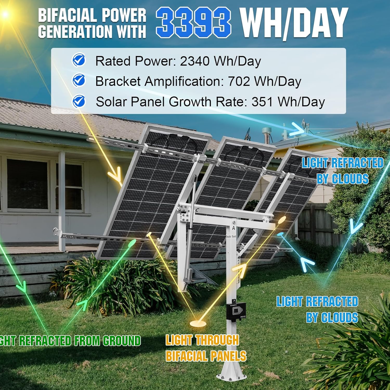
Figure 3.2.1: Attaching the B-Rod
Step 3.3: Install the C-Rod
From Screw Bag 3, retrieve two M8x40mm hex socket shoulder screws and two M8 flange nuts. Install the C-Rod onto the B-Rod. Secure it firmly with the screw nuts.

Figure 3.3.1: Attaching the C-Rod
Step 3.4: Install the D-Rod
From Screw Bag 4, take out four M8x80mm hex socket cap bolts, four M8 flange nuts, four M8 elastic washers, and four 8x16x1mm flat washers. Place the D-Rod onto the B-Rod and secure it using these components.

Figure 3.4.1: Attaching the D-Rod
Step 3.5: Install the E-Rod
Take out the two E-Rods. From Screw Bag 5, retrieve eight M8x80mm hex socket cap bolts, eight M8 flange nuts, eight M8 elastic washers, and eight 8x16x1mm flat washers. Install and fix the E-Rods from top to bottom using these fasteners.

Figure 3.5.1: Attaching the E-Rods
Step 3.6: Install Linear Actuator Stands
From Screw Bag 7, take out six M8x25mm hex socket cap bolts. Use these bolts to install the two silver linear actuator stands and the white linear actuator stand onto the frame.

Figure 3.6.1: Installing Actuator Stands
Step 3.7: Install Manual Rod Rack and Manual Rod
Fix the manual rod rack to the main pole using two M8x25mm hex socket cap bolts. Connect the B-Rod and the manual rod with an M6x35mm latch. Then, fix the manual rod to the manual rod rack using a 8xM6x30mm hex socket shoulder screw, two 8x24x2mm flat washers, and an M6 flange nut.

Figure 3.7.1: Manual Rod and Rack Assembly
Step 3.8: Install 300mm Linear Actuator
From Screw Bag 8, take out two M6x35mm latches and R-type cotter pins. Install the 300mm linear actuator into its designated position on the tracker frame, securing it with the retrieved components.

Figure 3.8.1: Linear Actuator Installation
Step 3.9: Place Channel Steel and Steel Connectors
Take out four pieces of 41x21x1.5mm-1150mm channel steel. Place them onto the E-Rods. Connect these channel steel pieces using two U-shaped connectors and two steel connectors. From Screw Bag 6, take out four M6x30x50mm square U-bolts, eight M10x30mm hexagonal socket cap bolts, eight M10 flange nuts, and six M6 flange nuts. Use these to securely fix the channel steel to the E-Rod.

Figure 3.9.1: Channel Steel Assembly
Step 3.10: Install the Sunlight Sensor
From Screw Bag 10, retrieve three M5x10mm hex socket cap bolts, two M8x25mm hex socket cap bolts, and two M8 flange nuts. Install the sunlight sensor rack onto the channel steel. After the rack is installed, mount the sunlight sensor onto the sunlight sensor rack, ensuring it faces the direction indicated in the diagram for optimal sun tracking.

Figure 3.10.1: Sunlight Sensor Installation
Step 3.11: Install Solar Panels
Carefully place the solar panels onto the single-axis solar tracker's channel steel. From Screw Bag 11, take out sixteen solar panel middle clamps and sixteen M8x22mm hex socket cap bolts. Use these components to securely install and fix the solar panels to the channel steel.

Figure 3.11.1: Solar Panels Mounted on Tracker
Step 3.12: Install Solar Tracker Controller
Install the solar tracker controller onto the main pole. Secure it using two M6x10mm hex socket cap bolts. Ensure all wiring connections from the solar panels and linear actuator are properly connected to the controller as per the wiring diagram (refer to controller manual for specific wiring details if needed).

Figure 3.12.1: Solar Tracker Controller Installation
4. Operating Instructions
The ECO-WORTHY Solar Panel Tracker System is designed for ease of use with intelligent tracking capabilities.
- Automatic Tracking Sunlight Mode: The system automatically tracks the sun's movement. Short press the 'SET' button to activate automatic tracking.
- One-Click Flat Bracket Mode: For situations requiring a flat panel position (e.g., during strong winds or for maintenance), long press the 'FLAT(M)' button for 3 seconds to manually set the brackets to a flat position. Long press again for 3 seconds to exit manual mode.
- Smart Screen Display: The controller features a smart screen display that shows battery capacity, working interface, and other operational information.
- Weatherproof Design: The controller is IP67 waterproof, ensuring reliable operation even in rainy conditions.
Figure 4.1: Solar Tracker Controller Interface
5. Maintenance
Regular maintenance ensures the longevity and optimal performance of your solar tracking system.
- Panel Cleaning: Periodically clean the surface of the solar panels to remove dust, dirt, and debris that can reduce efficiency. Use a soft cloth and water.
- Structural Inspection: Annually inspect all bolts, nuts, and connections for tightness. Re-tighten any loose fasteners to ensure structural integrity.
- Actuator and Moving Parts: Check the linear actuator and other moving parts for any signs of wear or obstruction. Keep them free from debris. Lubricate moving joints as recommended by the manufacturer (refer to specific component manuals if available).
- Cable Management: Ensure all cables are securely fastened and not exposed to sharp edges or excessive tension. Inspect for any signs of damage or fraying.
- Weather Preparedness: In anticipation of extreme weather conditions (e.g., very strong winds, heavy snow), consider activating the 'Flat Bracket Mode' to protect the panels and tracker mechanism. The system is designed to withstand strong winds up to 17.2 m/s.

Figure 5.1: System Durability in Adverse Weather
6. Troubleshooting
If you encounter issues with your solar tracker system, refer to the following common problems and their solutions:
| Problem | Possible Cause | Solution |
|---|---|---|
| Tracker not moving/tracking | Power supply issue, sensor obstruction, controller error, loose connections. | Check power connections to the controller and actuator. Ensure sunlight sensor is clean and unobstructed. Verify all wiring is secure. Restart the controller if possible. |
| Low power generation | Dirty solar panels, incorrect panel angle, partial shading, faulty panel. | Clean solar panels. Check if the tracker is correctly following the sun. Ensure no objects are casting shadows on the panels. Inspect panels for visible damage. |
| Unusual noises from tracker | Loose components, debris in moving parts, actuator issue. | Inspect all mechanical connections and tighten any loose bolts. Remove any debris from the actuator and moving parts. If noise persists, contact support. |
| Controller display not working | No power, damaged screen. | Check power input to the controller. Ensure connections are secure. If still unresponsive, contact support. |
For issues not listed above or if solutions do not resolve the problem, please contact ECO-WORTHY customer support.
7. Specifications
Key specifications for the ECO-WORTHY 600W Solar Panel Tracker System:
| Feature | Detail |
|---|---|
| Product Title | ECO-WORTHY 600W Solar Panel Tracker System: 3pcs Bifacial 195W Monocrystalline Solar Panels, Single-Axis Solar Tracking Kit with Tracker Controller for Shed Farm Yard Hut Field and Any Off-Grid |
| Brand | ECO-WORTHY |
| Model Number | L02M195TM-T1-3 |
| Solar Panel Type | Bifacial 195W Monocrystalline Solar Panels (3 pcs) |
| Total System Power | 600W (3 x 195W panels) |
| Tracking Type | Single-Axis Solar Tracking |
| Power Generation Increase | At least 30% compared to fixed mounts |
| Ideal Daily Output | Approx. 3.6KWh per day (under 4 hours full sunlight) |
| Panel Dimensions (each) | 59.2 x 28.3 x 2.2 inches (approx. 150.4 x 71.9 x 5.6 cm) |
| Tracker Angular Adjustment | 270° |
| Wind Resistance | Withstands strong winds of 17.2 m/s (Level 8) |
| Controller IP Rating | IP67 (Weatherproof) |
| Ground Space Required | 111in * 106in (approx. 2.82m * 2.69m) |
| Height | 3.93ft (approx. 1.2m) |
| Item Weight | 20.5 pounds (for the product, not the full system) |
8. Warranty & Support
ECO-WORTHY provides comprehensive quality support for its products:
- Main Frame: 3 years of quality support, with an additional 2 years available (total 5 years).
- Controller: 3 years of quality support.
- Other Accessories: 1 year of quality support.
For technical assistance, warranty claims, or any product-related inquiries, please contact ECO-WORTHY customer service through their official channels or the platform where the product was purchased. Please have your model number (L02M195TM-T1-3) and purchase details ready when contacting support.
Ask a question about this manual
Ask about setup, troubleshooting, compatibility, parts, safety, or missing instructions. Manuals+ will review the question and use this page’s manual context to help answer it.