
1. Introduction
Thank you for choosing the Electrobot 4 Channel Smart WiFi Switch. This device is designed to transform your home into a smart haven by allowing you to control up to four appliances remotely via the Smart Life app, Google Voice, or Amazon Alexa. This manual provides detailed instructions for installation, operation, and troubleshooting to ensure a seamless smart home experience.
Please read this manual thoroughly before installation and use, and retain it for future reference.
2. Key Features
- 4 Independent Channels: Control up to four separate appliances using your smartphone for maximum flexibility.
- Smart Life App Compatible: Easily manage and monitor connected devices through the user-friendly Smart Life app (iOS and Android).
- Voice Control Integration: Seamlessly works with Google Voice and Amazon Alexa for hands-free control.
- Compact and Versatile Design: Small size allows for easy installation in various locations.
- Simple Installation: Quick and straightforward wiring and app configuration.
- Remote Access Anywhere: Control your appliances from any location with an internet connection.
- Energy Efficiency: Schedule appliances to turn on or off at specific times to reduce energy consumption.
- Reliable and Secure: Ensures stable connections and smooth performance for your smart home setup.
- Wide Voltage Range: Supports 100-240V AC, suitable for various home appliances.
- Temperature Resistant: Operates effectively in a wide temperature range (-10°C to 40°C).
3. Product Specifications
| Specification | Value |
|---|---|
| Model Number | DIY-AC04-TY / EB-4CH-WSW |
| Voltage | 100-240V AC |
| Max Load per Channel | 10 Amps |
| Total Wattage | 2200 Watts |
| WiFi Standard | 2.4GHz b/g/n |
| Dimensions (L x W x H) | 9 x 8 x 2.7 Centimeters |
| Operating Temperature | -10°C to 40°C |
| Control Method | Remote, Voice |
| Controller Type | Google Assistant, Amazon Alexa, iOS, Android |
| Connectivity Protocol | Wi-Fi |
| Item Weight | 100 g |
| Included Components | Wifi Switch |
4. Safety Information
Please observe the following safety precautions to prevent damage to the device or personal injury:
- Ensure power is disconnected before performing any wiring or installation.
- Installation should be performed by a qualified electrician if you are unsure about electrical wiring.
- Do not exceed the maximum load rating of 10 Amps per channel or 2200 Watts total.
- Keep the device away from water, moisture, and high temperatures.
- Do not attempt to disassemble or repair the device yourself. Contact support if issues arise.
- Ensure the device is installed in a well-ventilated area.
5. Setup and Installation
5.1. Physical Installation and Wiring
The Electrobot 4 Channel Smart WiFi Switch requires careful wiring. Always ensure the main power supply is turned off before beginning any electrical work.

Figure 5.1: Detailed view of the Electrobot Smart WiFi Switch circuit board, showing input terminals (Input 1: USB 5V, Input 2: DC/AC 7-32V), GND in, Mode Switch Button, and WiFi/RF pairing buttons. The output terminals (NC, COM, NO) for each of the four channels are clearly visible at the top.

Figure 5.2: Front view of the Electrobot Smart WiFi Switch, indicating the USB 5V input, AC85-265V input, Reset button, and output terminals (NO, COM, NC) for each channel. The model number DIY-AC04-TY, max current 10A, and WiFi standard 2.4GHz are also displayed.
Wiring Instructions:
- Power Input: The module supports two power input options:
- USB 5V: Connect a standard 5V USB power supply to the USB port.
- DC/AC 7-32V: Connect a DC power supply (7-32V) or an AC power supply (7-32V) to the designated input terminals (Input 2).
- AC 85-265V: For direct AC mains power, connect to the AC85-265V input terminals as shown in Figure 5.2.
- Appliance Connection: Each of the four channels has three terminals:
- NO (Normally Open): The circuit is open (disconnected) when the relay is off, and closed (connected) when the relay is on.
- COM (Common): This is the common terminal for the relay.
- NC (Normally Closed): The circuit is closed (connected) when the relay is off, and open (disconnected) when the relay is on.
- Wiring Diagrams: Refer to the following diagrams for common wiring scenarios:

Figure 5.3: Wiring diagram illustrating how to connect AC and DC motors to the Electrobot Smart WiFi Switch. Note that only one motor can run at a time in this configuration. The diagram shows input power (85-250V AC or 7-32V DC) connected to the module, and the motor connected to the relay outputs.

Figure 5.4: Wiring diagram demonstrating how to connect an AC contactor to the Electrobot Smart WiFi Switch. The diagram shows the AC input (85-250V) to the module, and the module's output (NO, COM, NC) connected to the contactor's control terminals (A1, A2), which then controls the load.
5.2. App Installation and Device Pairing
The Electrobot Smart WiFi Switch works with the Smart Life app. Follow these steps to set up your device:
- Download the Smart Life App: Search for "Smart Life" in the Apple App Store (iOS) or Google Play Store (Android) and download the app.
- Register/Log In: Open the app and register for a new account or log in if you already have one.
- Add Device:
- Ensure your phone is connected to a 2.4GHz Wi-Fi network.
- Power on the Electrobot Smart WiFi Switch.
- In the Smart Life app, tap the "+" icon in the top right corner to add a device.
- Select "Electrical" or "Switch (Wi-Fi)" from the device list.
- Enter Pairing Mode: Press and hold the "WiFi Pairing button" on the module (refer to Figure 5.1) for about 5-7 seconds until the Wi-Fi indicator light starts blinking rapidly.
- Confirm the indicator is blinking rapidly in the app and proceed.
- Enter your Wi-Fi network password and confirm.
- The app will begin connecting to the device. Once connected, you can rename the device and assign it to a room.

Figure 5.5: The Electrobot Smart WiFi Switch highlighting its compatibility with Tuya and Smart Life applications, as well as integration with voice control platforms like Amazon Alexa and Google Assistant.
6. Operating Instructions
6.1. App Control (Smart Life App)
Once the device is successfully paired, you can control it from the Smart Life app:
- Open the Smart Life app and select your Electrobot Smart WiFi Switch from the device list.
- You will see individual controls for each of the four channels. Tap to turn channels on or off.
- Scheduling: Use the scheduling feature to set specific times for your appliances to turn on or off automatically.
- Timer: Set countdown timers for temporary control.
- Scene Automation: Create custom scenes to control multiple devices with a single tap or based on conditions (e.g., "Good Morning" scene turns on lights and coffee maker).
- Share Control: Share device control with family members through the app.
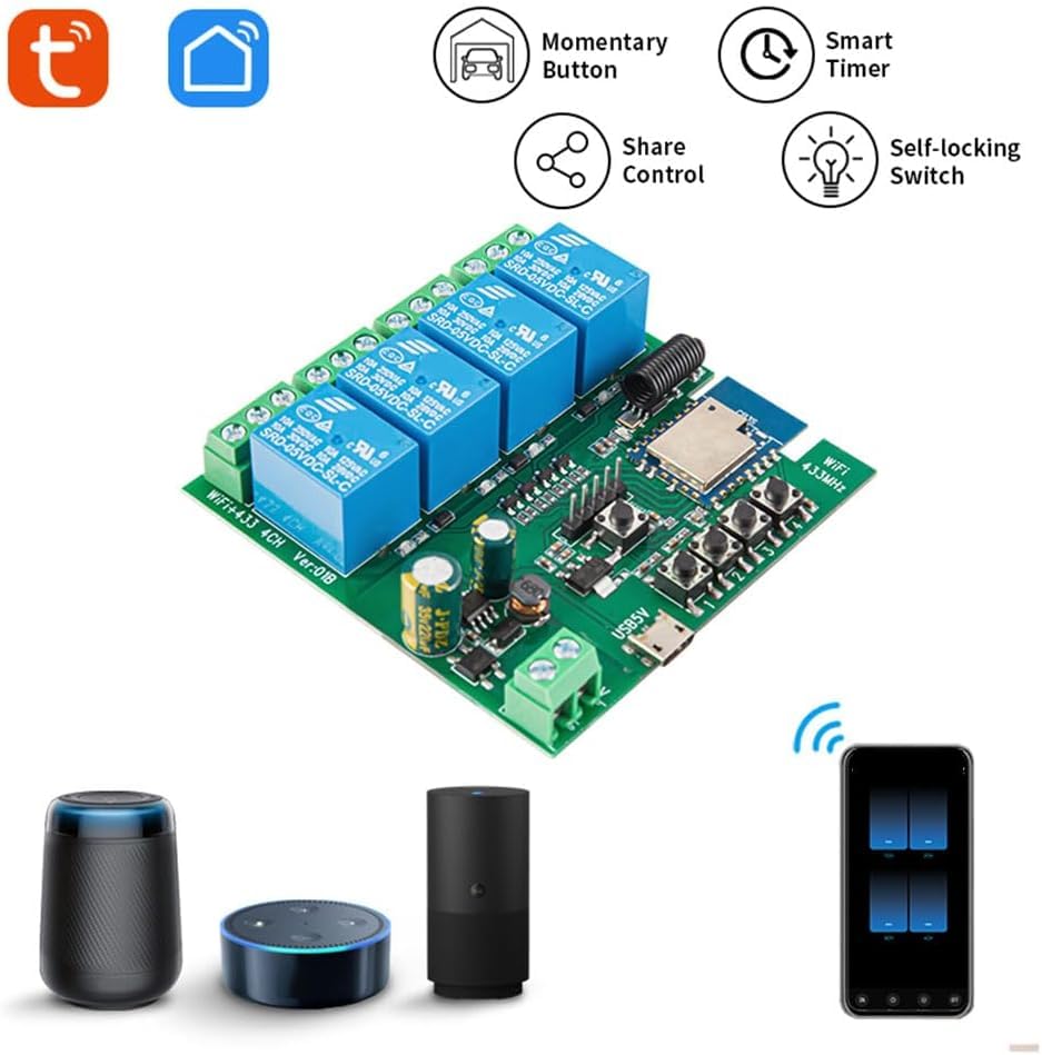
Figure 6.1: An illustration of the Smart Life app interface, demonstrating how a single mobile phone can control four separate devices connected to the Electrobot Smart WiFi Switch. It also shows integration with smart speakers for voice control.
6.2. Voice Control (Google Assistant & Amazon Alexa)
To enable voice control, link your Smart Life account with Google Assistant or Amazon Alexa:
- For Amazon Alexa:
- Open the Alexa app.
- Go to "Skills & Games" and search for "Smart Life".
- Enable the Smart Life skill and link your Smart Life account using your credentials.
- Discover devices. Once discovered, you can control your channels by saying, "Alexa, turn on [Device Name] Channel 1" or "Alexa, turn off the bedroom light."
- For Google Assistant:
- Open the Google Home app.
- Tap "+" > "Set up device" > "Works with Google".
- Search for "Smart Life", select it, and link your Smart Life account.
- Once linked, you can control your channels by saying, "Hey Google, turn on [Device Name] Channel 2" or "Hey Google, turn off the fan."

Figure 6.2: An example of using voice control with a smart speaker (Google Home) to operate a connected appliance, such as turning off a bedroom light.
7. Maintenance
- Keep the device clean and free from dust. Use a dry, soft cloth for cleaning.
- Do not use liquid cleaners or aerosols.
- Ensure proper ventilation around the device to prevent overheating.
- Regularly check wiring connections for tightness and signs of wear.
- Periodically check for Smart Life app updates to ensure optimal performance and security.
8. Troubleshooting
| Problem | Possible Cause | Solution |
|---|---|---|
| Device not connecting to Wi-Fi. | Incorrect Wi-Fi password, 5GHz Wi-Fi network, device too far from router, incorrect pairing mode. |
|
| Appliance not responding to control. | Incorrect wiring, power issue, relay failure. |
|
| Voice control not working. | Smart Life skill/service not linked, incorrect device name, internet connectivity issue. |
|
| Product received does not match description/model. | Shipping error, mislabeling. |
|
9. Warranty and Support
Specific warranty information for the Electrobot 4 Channel Smart WiFi Switch is not provided in this manual. Please refer to the product packaging or the retailer's website for warranty details.
For technical support, troubleshooting assistance, or any inquiries regarding your Electrobot product, please contact Electrobot customer service through the contact information provided at the point of purchase or on the official Electrobot website.
Manufacturer: Electrobot pvt ltd
Included Components: Wifi Switch