1. Introduction
This manual provides essential information for the safe and effective installation, operation, and maintenance of the DDORUU ST9120C Furnace Fan Control Board. This board serves as a replacement for various Honeywell ST9120 series and 40403 series furnace fan control circuit boards. Please read this manual thoroughly before proceeding with any procedures.
2. Safety Information
WARNING: Electrical Shock Hazard. Disconnect power before installation or servicing.
- Always turn off the main power supply to the furnace at the circuit breaker or fuse box before attempting any installation, maintenance, or troubleshooting.
- This product should be installed by a qualified technician. Improper installation can lead to property damage, serious injury, or death.
- Ensure all wiring connections are secure and comply with local electrical codes.
- Do not operate the furnace with damaged wiring or components.
3. Product Overview
The DDORUU ST9120C is a furnace fan control board designed to manage the operation of the furnace blower and inducer motors. It is a direct replacement for the following models:
- Honeywell 40403-001
- Honeywell 40403-002
- Honeywell 40403-003
- Honeywell ST9120A
- Honeywell ST9120B
- Honeywell ST9120C
This control board integrates essential functions for furnace operation, including fan control, inducer control, and safety features.

Figure 1: Top-down view of the DDORUU ST9120C Furnace Fan Control Board, showing various components, relays, and connection terminals.
4. Specifications
| Feature | Specification |
|---|---|
| Model Number | ST9120C |
| Replaces | 40403-001, 40403-002, 40403-003, ST9120A, ST9120B, ST9120C |
| Maximum Blower Loading (120 VAC) | 15FLA, 30LRA |
| Maximum Blower Loading (240 VAC) | 7.5FLA, 15LRA |
| Maximum Inducer Loading (120 VAC) | 3FLA, 10LRA |
| Maximum Inducer Loading (240 VAC) | 1.5FLA, 5LRA |
| Humidifier Terminal | 0.8A @ 115 VAC |
| Electronic Air Cleaner Terminal | 0.8A @ 115 VAC |
| 24V Circuit Protection | 5 amp replaceable automotive type fuse |
| Product Dimensions | 6.29 x 5.09 x 1.57 inches |
| Item Weight | 7 ounces |
5. Setup and Installation
Before You Begin:
- Ensure the main power to the furnace is OFF.
- Wear appropriate personal protective equipment (PPE).
- Have necessary tools ready (e.g., screwdriver, wire strippers, multimeter).
Installation Steps:
- Power Disconnection: Locate the circuit breaker for your furnace and switch it to the OFF position. Verify power is off using a multimeter.
- Access the Existing Board: Open the furnace access panel to expose the existing control board.
- Document Wiring: Before disconnecting any wires, take clear photos of the existing wiring connections. Label each wire if necessary to ensure correct re-connection.
- Disconnect Wires: Carefully disconnect all wires from the old control board.
- Remove Old Board: Unscrew or unclip the old control board from its mounting.
- Inspect New Board: Before installing, visually inspect the new DDORUU ST9120C board for any visible damage or loose components. Ensure all terminals are securely soldered.
- Mount New Board: Secure the new DDORUU ST9120C board in the same location as the old one, using the existing mounting hardware.
- Connect Wiring: Refer to your documented photos and labels to reconnect all wires to the corresponding terminals on the new board. Ensure all connections are firm and correct.
- Check Fuse: Verify the 5 amp automotive type fuse is correctly seated in its holder on the board.
- Close Panel: Securely close the furnace access panel.
- Restore Power: Turn the main power supply back ON at the circuit breaker.
- Test Operation: Initiate a heating or cooling cycle to verify the furnace and fan operate correctly.
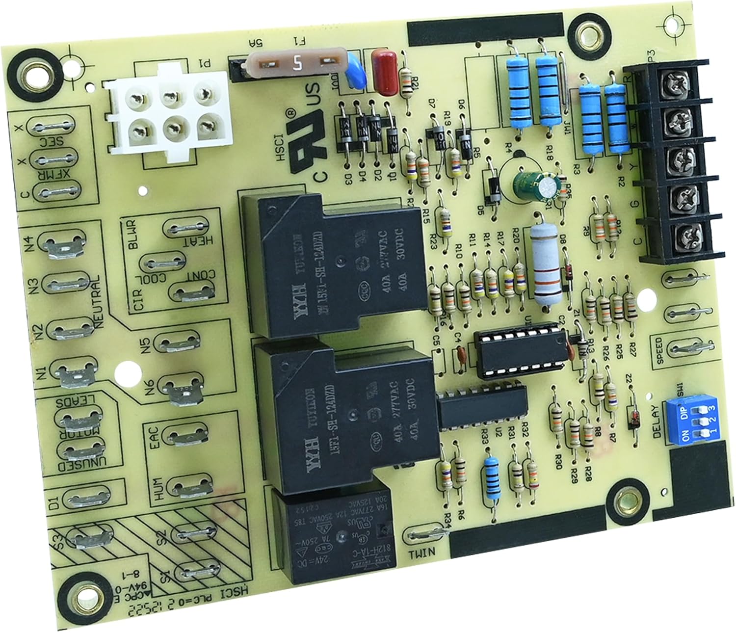
Figure 2: Angled view of the control board, highlighting the fuse and main power connector. Always disconnect power before handling.

Figure 3: Side view showing the various terminal connections for blower, heat, cool, inducer, and other furnace components.
6. Operating Instructions
The DDORUU ST9120C control board operates automatically in conjunction with your furnace thermostat and other safety controls. It manages the timing and sequencing of the furnace's components, primarily the blower fan and inducer motor, during heating and cooling cycles.
Key Functions:
- Blower Control: Activates and deactivates the main furnace blower fan based on thermostat calls for heat or cool, and internal timing sequences.
- Inducer Control: Manages the inducer motor operation for proper combustion air flow.
- Safety Monitoring: Integrates with furnace safety limits to ensure safe operation.
- Delay Settings: Features adjustable delay settings (via DIP switches) for blower on/off cycles, which can be configured by a qualified technician.

Figure 4: Close-up of the DIP switches, labeled 'DELAY ON DIP', used for adjusting blower timing settings. Consult your furnace manual or a technician for proper configuration.
7. Maintenance
The DDORUU ST9120C Furnace Fan Control Board is designed for reliable operation and generally requires minimal maintenance. However, periodic checks can help ensure its longevity and proper function.
Recommended Checks (Perform Annually or as needed):
- Power Disconnection: Always turn off power to the furnace before any inspection.
- Visual Inspection: Carefully inspect the board for any signs of overheating (discoloration), burnt components, or loose connections.
- Wiring Integrity: Ensure all wires connected to the board are secure and free from damage.
- Fuse Check: Inspect the 5 amp automotive fuse. If it appears blown or damaged, replace it with a fuse of the exact same rating.
- Cleanliness: Gently remove any dust or debris from the board using a soft brush or compressed air. Avoid using liquids.

Figure 5: An alternative angled view of the control board, useful for identifying component locations during inspection.
8. Troubleshooting
If your furnace is not operating as expected after installing the DDORUU ST9120C control board, consider the following troubleshooting steps. Always ensure power is disconnected before inspecting the board or wiring.
| Symptom | Possible Cause | Solution |
|---|---|---|
| Furnace does not turn on (no heat/cool, no fan) | No power to the board; Blown fuse; Incorrect wiring. | Check circuit breaker. Inspect and replace the 5 amp fuse if blown. Verify all wiring connections are correct and secure. |
| Blower fan does not run in AUTO mode, but runs in ON mode | Faulty relay on the control board; Incorrect DIP switch settings. | This may indicate a board component failure. Consult a qualified technician. Verify DIP switch settings are appropriate for your furnace. |
| Blower fan runs continuously | Stuck relay; Incorrect thermostat setting; Incorrect DIP switch settings. | Check thermostat setting (ensure it's not set to "Fan ON"). Consult a qualified technician to check relays and DIP switch settings. |
| No inducer motor operation | Incorrect wiring; Faulty inducer motor; Board issue. | Verify inducer motor wiring. Consult a qualified technician to diagnose the inducer motor and board. |
| Loose or unsoldered terminal | Manufacturing defect. | If identified upon initial inspection, contact the seller for replacement. Do not attempt to repair unless qualified. |
If these steps do not resolve the issue, it is recommended to contact a qualified HVAC technician for further diagnosis and repair.

Figure 6: A different angle of the control board, providing another view of the components and connections for troubleshooting purposes.

Figure 7: A detailed view of the control board, useful for identifying specific terminals and components during troubleshooting or installation.
9. Warranty and Support
The manufacturer does not provide specific warranty information in the product details. For any warranty-related inquiries, technical support, or assistance with installation and troubleshooting, please contact the seller or manufacturer directly through your purchase platform.
It is recommended to retain your proof of purchase for any support claims.


