1. Introduction
This manual provides comprehensive instructions for the installation, operation, and maintenance of your JN Electric Bike Controller. Designed for electric scooters and e-bikes, this brushless motor controller offers versatile performance for various electric vehicle applications. Please read this manual thoroughly before use to ensure proper function and safety.
2. Safety Information
Important Safety Warning: It is illegal to ride electric scooters on public roads, pavements, or cycle paths in many regions. They are intended only for use on private land with the owner's permission. Always check local regulations before operating your electric vehicle.
- Ensure all connections are secure and properly insulated before applying power.
- Do not attempt to open or modify the controller casing, as this may void the warranty and pose electrical hazards.
- Keep the controller away from water, excessive heat, and direct sunlight.
- Always disconnect power before performing any maintenance or installation procedures.
- Verify voltage compatibility (24V/36V/48V) with your motor and battery system before connecting.
3. Product Overview and Features
The JN Electric Bike Controller is a high-performance brushless DC motor controller designed for optimal efficiency and reliability. It features advanced sine wave technology for smooth operation and comprehensive protection mechanisms.
- Powerful Controller: Supports 24V/36V/48V systems with a maximum current of 30±1A and power range of 750-1000W. Compatible with both Hall and non-Hall motors.
- Three-Mode Operation: Offers enhanced riding flexibility to suit different terrains, weather conditions, or personal preferences.
- Sine Wave Technology: Delivers smoother motor operation, reduced noise, and improved overall efficiency for a quieter, more comfortable ride.
- Comprehensive Protection: Equipped with low voltage protection (DC30/40±0.5V) to safeguard your e-bike's electrical system.
- Durable Construction: Made from aluminum and plastic for durability and effective heat dissipation.
- Easy Installation: Compact size (145*60*36mm) and lightweight design (approx. 390g) for straightforward integration. Compatible with UART No.2 protocol.

Figure 3.1: The JN Electric Bike Controller with its various wiring harnesses.
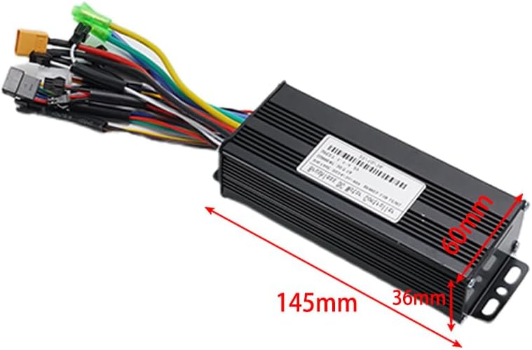
Figure 3.2: Dimensions of the controller, approximately 145mm x 60mm x 36mm.
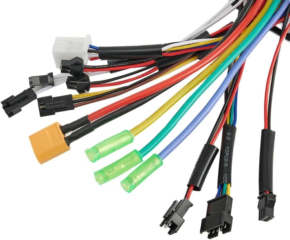
Figure 3.3: Close-up view of the various wire connectors for different functions.
4. Specifications
| Specification | Value |
|---|---|
| Maximum Current | 30±1A |
| Power | 750-1000W |
| Rated Voltage | DC24V/36V/48V |
| Speed Setting | 1.1-4.2V |
| Rated Current | 15A |
| Mosfets | 12 mos |
| Brake Input | Low level |
| Low Voltage Protection | DC30/40±0.5V |
| Material | Aluminum + Plastic |
| Color | Black |
| Controller Size (Approx.) | 145mm x 60mm x 36mm |
| Weight (Approx.) | 390g |
| Model Type | Three mode |
| Compatibility | UART No.2 protocol controller, Hall and non-Hall motors |
5. Setup and Installation
5.1 Package Contents
- 1 x JN Electric Bike Controller
5.2 Installation Steps
Before beginning installation, ensure your electric vehicle's power is completely off and the battery is disconnected.
- Mount the Controller: Select a secure and dry location on your e-bike or scooter for mounting the controller. Use the integrated mounting brackets and appropriate fasteners to firmly attach the controller. Ensure adequate airflow around the controller for heat dissipation.

Figure 5.1: Side view showing the mounting brackets on the controller.
- Connect Motor Wires: Connect the three main motor phase wires (usually green, yellow, blue) from your motor to the corresponding wires on the controller. If your motor has Hall sensors, connect the Hall sensor wires (typically a small 5-wire connector) to the controller's Hall sensor port. This controller is compatible with both Hall and non-Hall motors.
- Connect Battery Power: Connect the main positive (+) and negative (-) power wires from your battery to the corresponding power input wires on the controller. Double-check polarity to prevent damage.
- Connect Throttle: Connect the throttle wire to the controller's throttle input. The speed setting is typically 1.1-4.2V.
- Connect Brake Levers: Connect the brake lever wires to the controller's brake input. This controller uses a low-level brake input.
- Connect Display/UART: Connect your UART No.2 protocol display to the designated UART port on the controller. This connection is crucial for displaying speed, battery level, and other operational data.
- Other Connections: Connect any other auxiliary wires such as pedal assist sensor (PAS), lights, or cruise control if applicable to your setup. Refer to your e-bike's specific wiring diagram for these connections.

Figure 5.2: Close-up of the wire entry point into the controller, showing various colored wires.
- Secure All Connections: Ensure all connections are tight and properly insulated to prevent short circuits or loose contacts during operation.
- Initial Test: Once all connections are made, carefully reconnect the battery. Perform a low-speed test in a safe, open area to verify proper function of the motor, throttle, and brakes.
Note: While this controller is designed for easy integration, a basic understanding of e-bike wiring is beneficial. If you are unsure about any wiring steps, it is recommended to consult a professional.
6. Operating Instructions
The JN Electric Bike Controller operates seamlessly with your e-bike's display and throttle. Once installed and powered on, the controller manages power delivery to the motor based on your input.
- Power On: Turn on your e-bike's main power switch. The display (if connected) should illuminate.
- Throttle Control: Gently twist the throttle to engage the motor. The controller will provide power according to the throttle input (1.1-4.2V speed setting).
- Three-Mode Operation: If your display or e-bike system supports it, you can switch between the controller's three operational modes. These modes typically adjust power output and acceleration characteristics for different riding conditions (e.g., Eco, Normal, Sport). Consult your display's manual for mode switching instructions.
- Braking: Activating the brake levers will cut power to the motor, ensuring safe stopping.
- Low Voltage Protection: The controller features built-in low voltage protection (DC30/40±0.5V). If the battery voltage drops below this threshold, the controller will reduce or cut power to protect the battery from over-discharge.
7. Maintenance
Proper maintenance ensures the longevity and optimal performance of your controller.
- Keep Clean: Regularly wipe the controller's exterior with a dry, soft cloth to remove dust and dirt. Avoid using harsh chemicals or abrasive cleaners.
- Check Connections: Periodically inspect all wiring connections for tightness and signs of wear or corrosion. Re-secure any loose connections.
- Avoid Moisture: While the controller is robust, prolonged exposure to heavy rain or submersion in water should be avoided. Ensure it is mounted in a location protected from direct water spray.
- Temperature Management: Ensure the controller has adequate ventilation, especially during prolonged high-power operation, to prevent overheating.
- Storage: If storing your e-bike for an extended period, disconnect the battery from the controller.
8. Troubleshooting
This section addresses common issues you might encounter with your JN Electric Bike Controller.
| Problem | Possible Cause | Solution |
|---|---|---|
| Motor not responding / No power |
|
|
| Motor runs intermittently or roughly |
|
|
| Controller overheating |
|
|
| Display not working or showing errors |
|
|
9. Warranty and Support
Cloudpower products are manufactured to high quality standards. While specific warranty details are not provided in this manual, please retain your proof of purchase for any warranty claims. For technical support, troubleshooting assistance, or inquiries regarding parts and service, please contact your retailer or the manufacturer directly through their official channels.
For further assistance, please visit the Cloudpower official website or contact their customer service department.