1. Introduction
This manual provides detailed instructions for the installation, operation, and maintenance of your Ohsilv MPPT Solar Charge Controller 100A. This device is designed to manage power flow from your solar panels to your battery bank, ensuring efficient charging and protecting your batteries from overcharge and over-discharge. It features automatic system voltage recognition for 12V, 24V, 36V, and 48V systems.
2. Product Overview
The Ohsilv MPPT Solar Charge Controller integrates advanced Maximum Power Point Tracking (MPPT) technology with Pulse Width Modulation (PWM) for high charging efficiency. It features an intuitive LCD display and multiple ports for solar input, battery connection, and DC load output.

Figure 2.1: Front view of the Ohsilv MPPT Solar Charge Controller. It shows the LCD screen, control buttons (RESET, MENU, ON/OFF), and indicators for solar, battery, and load connections. The display dynamically shows operational data.
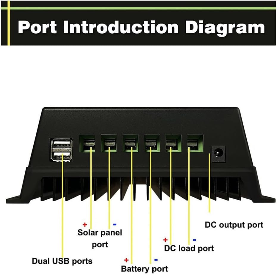
Figure 2.2: Port Introduction Diagram. This image clearly labels the connection points on the controller: Dual USB ports, Solar panel port (positive and negative), Battery port (positive and negative), DC load port (positive and negative), and a DC output port.

Figure 2.3: LCD Display Details. This diagram illustrates the various sections of the LCD: (1) Battery status (voltage, current), (2) Solar panel status (voltage, current), (3) Load status (current, temperature, time ON/OFF), (4) Operate Mode Select (Charging, Light control and delay, Universal Control, Manual, Timing, Test), and (5) OK/Fault indicator.
3. Key Features
- User-Friendly LCD Display: Dynamically shows operation data and equipment status, including battery voltage, PV charging current, battery discharge current, product operating temperature, and delay time.
- Advanced MPPT Technology: Utilizes an advanced Maximum Power Point Tracking algorithm for rapid tracking of the PV array's maximum power point, achieving tracking efficiency of not less than 99.5%.
- Automatic System Voltage Recognition: Automatically detects 12V, 24V, 36V, and 48V battery systems.
- Multifunctional Design: Features a backlit LCD with clock display and 7 operating modes: Charge Mode, Light Control Mode, Light Control + Time Delay Mode, Universal Control Mode, Manual Control Mode, and Timing Control Mode.
- Safe Voltage Protection: Includes comprehensive protection against battery overvoltage, overcurrent, power failure, overload, deep discharge, reverse connection, and over-temperature.
- Dual USB Charging Ports: Provides 5V USB output for charging mobile phones and other USB devices.
- Multiple Battery Type Compatibility: Supports Seal, GEL, Flooded, and LifePO4 battery charging.
4. Safety Instructions
Please read all instructions carefully before installation and operation. Failure to follow these instructions may result in damage to the unit, personal injury, or property damage.
- Ensure all connections are tight and correct to avoid excessive voltage drop and potential overheating.
- Connect the battery to the charge controller first, then the solar panel, and finally the load. Disconnect in the reverse order.
- Install the controller indoors, away from direct sunlight, high temperatures, and water.
- Ensure adequate ventilation around the controller to prevent overheating.
- The controller generates heat during operation; mount it on a non-flammable surface.
- Use appropriate circuit breakers or fuses for the solar panel, battery, and load circuits.
- Do not attempt to disassemble or repair the controller yourself. Contact qualified personnel for service.
- Wear eye protection when working with batteries.
5. Setup and Installation
5.1 Mounting the Controller
Mount the controller vertically on a wall or a stable surface, ensuring there is sufficient air circulation around the unit for heat dissipation. Avoid mounting in direct sunlight or areas with high humidity.
5.2 Wiring Connections
Follow the connection order strictly to prevent damage to the controller or other components.
- Connect the Battery: Connect the battery to the battery terminals on the controller (marked with a battery symbol). Ensure correct polarity (+ to + and - to -). The controller will automatically detect the battery voltage (12V/24V/36V/48V).
- Connect the Solar Panel: Connect the solar panel to the solar terminals on the controller (marked with a solar panel symbol). Ensure correct polarity.
- Connect the DC Load: Connect the DC load to the load terminals on the controller (marked with a light bulb symbol). Ensure correct polarity.
Important: Always connect the battery first, then the solar panel, and finally the load. Disconnect in the reverse order: load, then solar panel, then battery.
6. Operating Instructions
6.1 LCD Display and Buttons
The LCD displays real-time system information. Use the buttons below the screen to navigate and adjust settings:
- RESET Button: Used to reset certain parameters or exit a menu.
- MENU Button: Used to enter the menu, cycle through display screens, and confirm selections.
- ON/OFF Button: Controls the DC load output.
6.2 Operating Modes
The controller offers 7 operating modes for the DC load output, configurable via the MENU button:
- Charge Mode: Standard battery charging.
- Light Control Mode: Load turns on automatically at dusk and off at dawn.
- Light Control + Time Delay Mode: Load turns on at dusk and stays on for a set duration.
- Universal Control Mode: Load is always on (unless battery voltage is low).
- Manual Control Mode: Load is controlled manually via the ON/OFF button.
- Timing Control Mode: Load turns on and off according to a set schedule.
- Test Mode: For system testing purposes.
6.3 USB Charging
The controller includes dual 5V USB ports for charging small electronic devices. These ports are active when the controller is powered by the battery.
7. Maintenance
Regular maintenance ensures optimal performance and longevity of your solar charge controller:
- Check Connections: Periodically inspect all wiring connections for tightness and corrosion. Loose connections can cause overheating and damage.
- Clean the Controller: Keep the controller clean and free of dust and debris. Use a dry cloth to wipe the exterior. Ensure ventilation openings are not blocked.
- Monitor Performance: Regularly check the LCD display for normal operation parameters and any fault indicators.
- Battery Inspection: Follow the battery manufacturer's maintenance guidelines for your specific battery type.
8. Troubleshooting
This section addresses common issues you might encounter with your solar charge controller.
| Problem | Possible Cause | Solution |
|---|---|---|
| Controller display is off / No power |
|
|
| Battery not charging |
|
|
| Load not working |
|
|
| Over-temperature warning |
|
|
9. Specifications
| Model | 500707471A3 |
| Brand | Ohsilv |
| Rated Current | 100A |
| System Voltage | 12V / 24V / 36V / 48V Auto-recognition |
| Product Dimensions | 20 x 20 x 7 cm |
| Product Weight | 729 g |
| Color | Blue |
| USB Output | Dual 5V USB ports |
| Battery Compatibility | Seal, GEL, Flooded, LifePO4 |
10. Warranty and Support
This product is designed for reliable operation. For any issues or questions not covered in this manual, please contact your retailer or the manufacturer's customer support. Please retain your proof of purchase for warranty claims.
As per the product information, the manufacturer is Ohsilv. For specific warranty terms and conditions, please refer to the documentation provided at the time of purchase or contact Ohsilv customer service.