1. Introduction
This manual provides detailed instructions for the installation, operation, and maintenance of the Pteanecay MT6835 Magnetic Encoder Module. The MT6835 is a high-precision 21-bit magnetic encoder designed for absolute angle measurement in brushless motor applications, offering both PWM and SPI interfaces.
Please read this manual thoroughly before using the module to ensure proper functionality and to prevent damage.
2. Product Overview
The MT6835 Magnetic Encoder Module utilizes advanced magnetic technology to provide absolute angle measurement from 0° to 360°. It is capable of outputting 21-bit angle data via a standard 4-wire SPI interface (up to 16MHz clock) and supports incremental output (ABZ) with resolutions from 1 to 16384 lines. Additionally, it supports UVW incremental output for 1-16 arbitrary pole pairs.
Key features include:
- 21-bit absolute angle measurement.
- Standard 4-wire SPI interface for data reading.
- Incremental ABZ output with configurable resolution.
- UVW output for brushless motor commutation.
- Support for up to 5 times online zero programming.
- Low system delay (2µs-10µs) and high-speed operation (up to 120,000 rpm).

Figure 2.1: MT6835 Magnetic Encoder Module mounted on a green circuit board, illustrating its compact design and integration capability.

Figure 2.2: Detailed view of the MT6835 module, highlighting the integrated circuit and connection pads.
3. Specifications
The following table outlines the technical specifications of the MT6835 Magnetic Encoder Module:
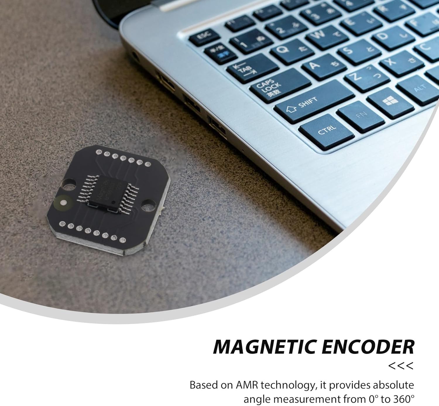
Figure 3.1: Visual representation of key specifications.
| Parameter | Value |
|---|---|
| Working Voltage | 3.3V ~ 5.0V |
| Working Temperature | -40°C ~ 125°C |
| Linearity Deviation (Typical) | Less than ±0.02° (self-calibration) |
| System Delay | 2µs ~ 10µs |
| Maximum Speed | Up to 120,000 rpm |
| Output Interface | PWM, SPI (4-wire), ABZ, UVW |
| Product Dimensions | 3.15 x 1.97 x 0.39 inches |
| Item Weight | 0.071 ounces |
| Model Number | 500737109 |
4. Setup
Proper setup is crucial for the accurate and reliable operation of the MT6835 module. Ensure all connections are secure and correct before applying power.
4.1. Components Required
- MT6835 Magnetic Encoder Module
- Appropriate magnet (typically a diametrically magnetized disc magnet)
- Microcontroller or host system with SPI/PWM capabilities
- Connecting wires/cables
- Regulated power supply (3.3V to 5.0V DC)
4.2. Installation Steps
- Mounting the Module: Securely mount the MT6835 module to your application's PCB or mounting surface. Ensure it is stable and free from vibrations.
- Magnet Placement: Position the magnet centrally above or below the MT6835 sensor. The air gap between the magnet and the sensor should be optimized for best performance, typically within 0.5mm to 3mm, as specified in the datasheet. The magnet must be diametrically magnetized.
- Power Connection: Connect the VCC pin of the module to a regulated 3.3V-5.0V DC power supply and the GND pin to the system ground.
- Interface Connection (SPI): If using SPI, connect the module's SPI pins (SCK, MISO, MOSI, CS) to the corresponding pins on your microcontroller.
- Interface Connection (PWM/ABZ/UVW): If using PWM, ABZ, or UVW outputs, connect the respective output pins to your motor controller or microcontroller inputs.
- Initial Power-Up: Apply power to the module. Observe any indicator LEDs (if present) for proper power-on.

Figure 4.1: MT6835 module shown with its corresponding magnet, illustrating the components involved in the setup.
5. Operating Instructions
The MT6835 module provides absolute angle data through its SPI interface and incremental signals for motor control.
5.1. SPI Communication
The module communicates via a 4-wire SPI interface. To read the 21-bit angle data:
- Initialize your microcontroller's SPI peripheral to communicate with the MT6835.
- Assert the Chip Select (CS) line low to begin communication.
- Send the appropriate command (refer to the MT6835 datasheet for specific SPI commands for angle reading and configuration).
- Read the 21-bit angle data from the MISO line. The data typically includes status bits along with the angle value.
- Deassert the CS line high to end communication.
The system delay for angle data acquisition is between 2µs and 10µs, allowing for high-speed applications.
5.2. Incremental Outputs (ABZ/UVW)
The MT6835 can provide standard incremental encoder signals (A, B, Z) and commutation signals (U, V, W) for brushless motors. These outputs are configurable:
- ABZ Output: Configurable from 1 to 16384 lines per revolution. Used for position and speed feedback in general motion control.
- UVW Output: Supports 1-16 arbitrary pole pairs, synchronized with the motor's electrical angle for precise commutation.
5.3. Online Zero Programming
The module supports up to 5 times online zero programming, allowing users to define a specific mechanical position as the zero-angle reference electronically. Refer to the MT6835 datasheet for the exact procedure for zero programming via SPI commands.
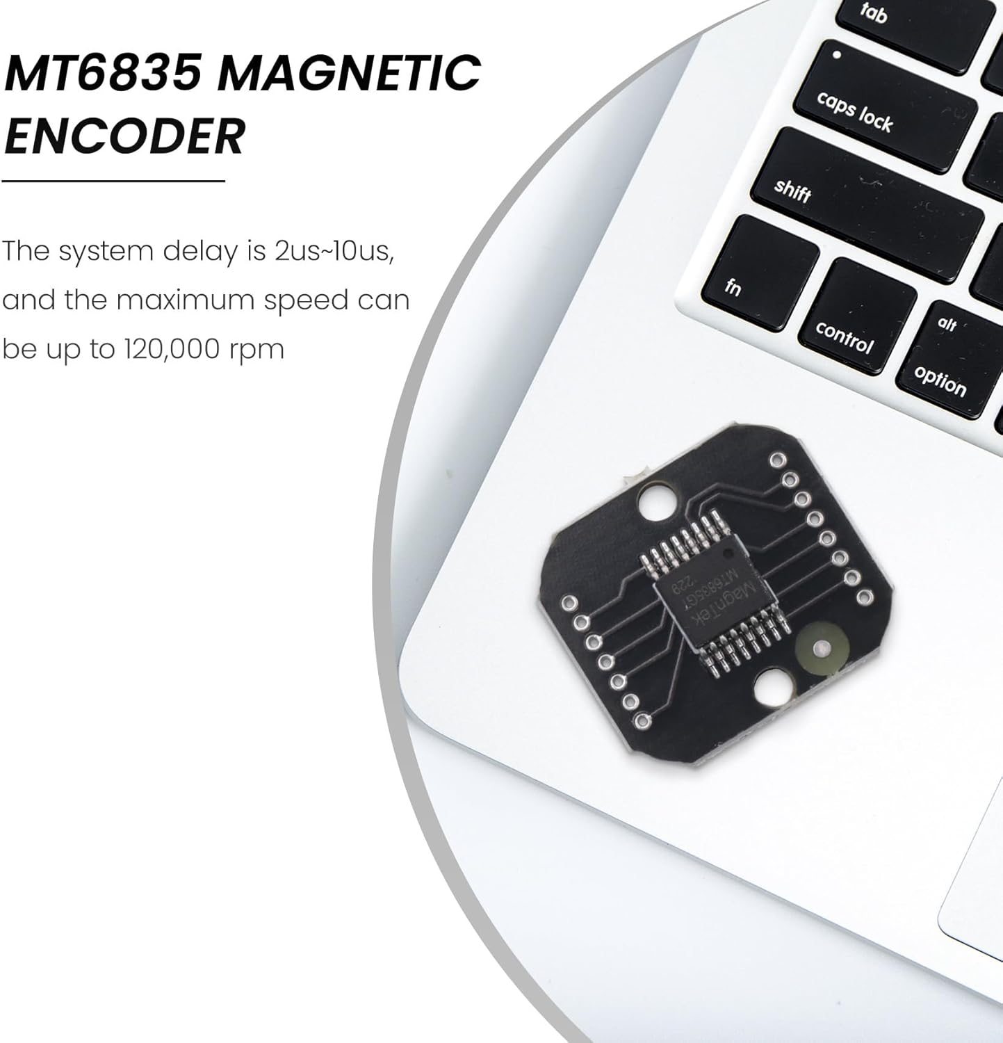
Figure 5.1: MT6835 module in a development context, indicating its use with a host system for programming and data acquisition.
6. Maintenance
The MT6835 Magnetic Encoder Module is designed for long-term reliability with minimal maintenance. However, following these guidelines can help ensure optimal performance:
- Cleaning: Keep the module free from dust, dirt, and moisture. If cleaning is necessary, use a soft, dry cloth. Avoid using solvents or abrasive cleaners.
- Environmental Conditions: Operate and store the module within the specified temperature range (-40°C to 125°C) and avoid extreme humidity.
- Physical Inspection: Periodically inspect the module and its connections for any signs of physical damage, loose wires, or corrosion.
- Magnet Integrity: Ensure the magnet remains securely positioned and free from damage or demagnetization, as this can affect accuracy.
7. Troubleshooting
If you encounter issues with the MT6835 module, consider the following troubleshooting steps:
- No Output/Incorrect Readings:
- Verify power supply voltage is within 3.3V-5.0V.
- Check all wiring connections for continuity and correct pin assignments (VCC, GND, SPI, ABZ/UVW).
- Ensure the magnet is correctly positioned and the air gap is within the recommended range.
- Confirm the magnet is diametrically magnetized.
- Review your microcontroller's SPI communication code for correct clock speed, mode, and data handling.
- Intermittent Readings:
- Check for electromagnetic interference (EMI) from nearby motors or power lines. Shielding may be required.
- Ensure stable power supply without voltage fluctuations.
- Verify secure physical mounting of both the module and the magnet.
- Module Not Responding:
- Confirm power is applied and the module is receiving sufficient current.
- Check for short circuits or damaged components on the module or connecting PCB.
For further assistance, consult the official MT6835 datasheet or contact technical support.
8. Warranty and Support
The Pteanecay MT6835 Magnetic Encoder Module is manufactured to high-quality standards. For information regarding warranty coverage, return policies, or technical support, please refer to the documentation provided at the point of purchase or contact Pteanecay directly through their official support channels.
When contacting support, please have your product model number (500737109) and a detailed description of the issue ready.