Introduction
This manual provides detailed instructions for the safe and efficient operation of the DC DC 2-24V to 3-30V 4A 80W Step Up Boost Converter CC CV Power Module. This module is designed to convert a lower DC input voltage to a higher DC output voltage, offering constant current (CC) and constant voltage (CV) regulation. It is suitable for various applications requiring adjustable regulated power supply, including charging batteries, driving LEDs, and powering electronic devices.
Product Overview
The module features input and output terminals, a USB output port, and potentiometers for adjusting output voltage and current. A heatsink is included for thermal management.

Figure 1: Top-down view of the DC DC Boost Converter module, showing the main components including the inductor, capacitors, input/output terminals, and USB port. A separate heatsink is shown below the module.

Figure 2: Angled view of the boost converter module, highlighting the input (IN-) and output (OUT+) screw terminals, the two adjustment potentiometers, and the USB output port.
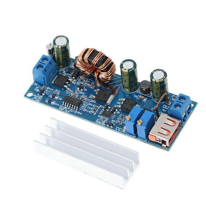
Figure 3: Close-up view of the central part of the module, showing the large inductor coil and various integrated circuits and capacitors, which are key to its boosting and regulation functions.

Figure 4: Close-up of the output section of the module, showing the USB Type-A output port and the screw terminals for the regulated DC output.

Figure 5: Bottom view of the boost converter module, displaying the model number "ZK-S4" and input/output voltage ranges "2V-24V" and "3V-30V".
Specifications
| Parameter | Value |
|---|---|
| Input Voltage Range | DC 2V - 24V |
| Output Voltage Range | DC 3V - 30V (Adjustable) |
| Maximum Output Current | 4 Amps |
| Maximum Output Power | 80 Watts |
| Conversion Efficiency | Up to 94% |
| Operating Temperature | -40°C to +85°C |
| Dimensions | (Approximate, based on typical modules) 68mm x 36mm x 15mm |
| Manufacturer | Generic |
| ASIN | B0D9KVPDGG |
Note: Efficiency and maximum power/current may vary based on input/output voltage difference and operating conditions. Adequate cooling (heatsink) is required for high power operation.
Setup Instructions
- Prepare Components: Ensure you have the boost converter module, a suitable DC power source (within 2V-24V), a multimeter for measuring voltage and current, and a load for testing.
- Connect Input Power:
- Connect the positive (+) terminal of your DC power source to the IN+ terminal on the module.
- Connect the negative (-) terminal of your DC power source to the IN- terminal on the module.
- Ensure correct polarity to prevent damage to the module.
- Connect Output Load:
- Connect the positive (+) terminal of your load to the OUT+ terminal on the module.
- Connect the negative (-) terminal of your load to the OUT- terminal on the module.
- Alternatively, for USB-powered devices, use the integrated USB Type-A port.
- Install Heatsink: For continuous operation at higher currents or power levels, attach the provided heatsink to the main power components (e.g., the large inductor and power ICs) using thermal adhesive or paste (not included). This helps dissipate heat and maintain performance.
Caution: Always ensure power is disconnected before making or changing any connections. Incorrect wiring can damage the module or connected devices.
Operating Instructions
- Initial Power On: After all connections are secure, apply power to the input terminals.
- Adjusting Output Voltage (CV Mode):
- Locate the potentiometer labeled "V-ADJ" or similar (usually the one closer to the output terminals).
- Using a small screwdriver, slowly turn this potentiometer clockwise to increase the output voltage, or counter-clockwise to decrease it.
- Monitor the output voltage with a multimeter connected to the OUT+ and OUT- terminals until the desired voltage is reached.
- It is recommended to adjust voltage with no load or a light load initially.
- Adjusting Output Current (CC Mode):
- Locate the potentiometer labeled "I-ADJ" or similar (usually the one closer to the input terminals or the other adjustment).
- To set the current limit, first set the output voltage slightly higher than the target load voltage.
- Connect an ammeter in series with your load, or short the output terminals (briefly and carefully, with a suitable current-limiting resistor if possible) and adjust the "I-ADJ" potentiometer.
- Turn the potentiometer clockwise to increase the current limit, or counter-clockwise to decrease it.
- The CC mode is primarily used for charging batteries or driving LEDs, where a constant current is desired.
- USB Output: The USB port provides a regulated 5V output, suitable for charging standard USB devices, provided the module's main output voltage is set appropriately or it has an internal 5V regulator for the USB port (common for these modules). Verify the voltage with a multimeter before connecting sensitive devices.
Maintenance
- Cleaning: Keep the module clean and free from dust and debris. Use a soft, dry brush or compressed air to remove dust. Do not use liquid cleaners.
- Inspection: Periodically inspect the module for any signs of damage, loose connections, or overheating (discoloration on components).
- Thermal Management: Ensure the heatsink is properly attached and that there is adequate airflow around the module, especially during high-power operation, to prevent overheating.
- Storage: Store the module in a dry, cool environment, away from direct sunlight and corrosive substances.
Troubleshooting
| Problem | Possible Cause | Solution |
|---|---|---|
| No output voltage |
|
|
| Output voltage unstable or fluctuating |
|
|
| Module overheating |
|
|
| Cannot adjust voltage/current |
|
|
Warranty and Support
This product is manufactured by Generic. For specific warranty information or technical support, please refer to the retailer or manufacturer's official website where the product was purchased. Keep your purchase receipt as proof of purchase.
For general inquiries regarding the operation of DC-DC converters, online resources and electronics forums can provide valuable assistance.