1. Product Overview
This manual provides detailed instructions for the installation, operation, and maintenance of your Huayong Dual Drive Motor Controller. Designed for electric bikes and scooters, this controller system efficiently manages two brushless motors, offering reliable performance and enhanced safety features. The system includes a main controller unit and an LCD display for monitoring and control.
2. Product Features
- Dual Mode Design: Ensures stable and consistent power assistance for both motors.
- High Sensitivity & Fast Response: Precision electronic components provide accurate control over vehicle direction and speed.
- Durable Construction: Controller shell is solid, lightweight, wear-resistant, and designed for various driving environments.
- Optimized Assisted Start: Prevents sudden acceleration or deceleration for improved safety.
- Easy Installation: Features color-coded wires for straightforward connection and setup.
- LCD Display: Provides essential ride information and settings, with a bracket for easy handlebar mounting (suitable for 22.2mm diameter handlebars).
- Voltage Versatility: Supports multiple voltage configurations (e.g., 36V, 48V, 60V, 72V) adjustable via the LCD display.
3. Setup and Installation
Carefully follow these steps to install your dual drive motor controller. Ensure the vehicle is powered off before beginning any installation.
3.1 Wiring Diagram for 3000W (1500W+1500W) Controller
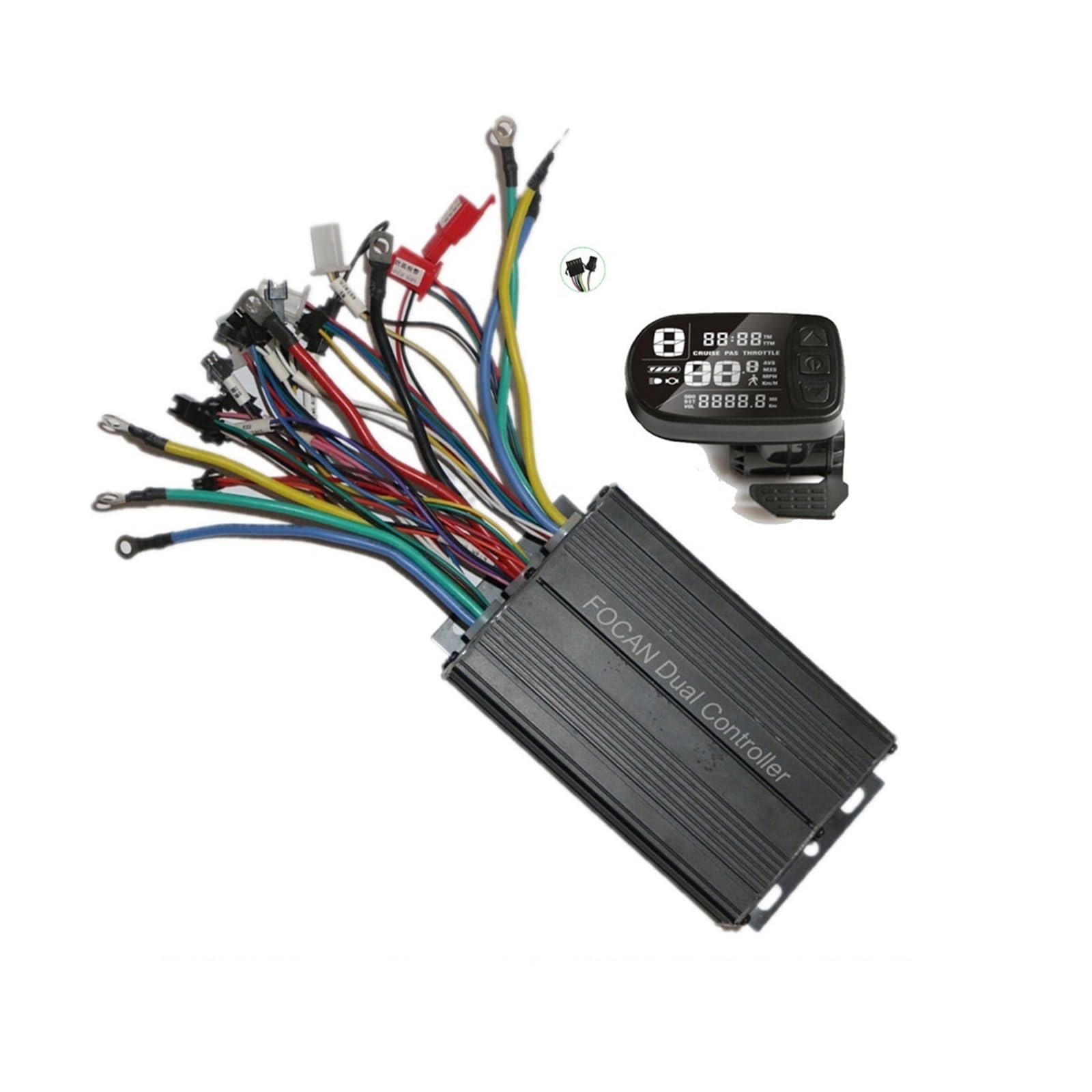
Figure 1: Wiring connections for the 3000W Huayong Dual Drive Motor Controller.
This diagram illustrates the connections for the 3000W controller. Identify and connect the following wires:
- Battery Power: Connect to your vehicle's battery. Ensure correct polarity.
- Motor 1 & Motor 2: Connect to the respective brushless motors.
- Throttle: Connect the throttle control unit.
- LCD Meter: Connect the display unit (SM 5-pin connector).
- Hall 1 & Hall 2: Connect the Hall sensor wires from each motor.
- Brake (Low Brake / High Brake): Connect your brake levers.
- Self-learn 1 & Self-learn 2: These wires are used for initial motor pairing. Connect them together briefly during the self-learning process (see Section 3.3).
- Voltage Choice: Used for setting the system voltage.
- Single/Double Drive Choice: Selects between single or dual motor operation.
- Reverse: For reverse function, if applicable.
- Alarm: Connect to an alarm system, if used.
- Soft Start: For a smoother initial acceleration.
3.2 Wiring Diagram for 1000W (500W+500W) Controller

Figure 2: Wiring connections for the 1000W Huayong Dual Drive Motor Controller.
This diagram details the connections for the 1000W controller. Note the differences in connector types and labels compared to the 3000W model:
- Power XT90: Main power input from the battery.
- Motor 1 & Motor 2: Connect to the respective brushless motors.
- Throttle: Connect the throttle control unit.
- LCD Display: Connect the display unit.
- Hall 1 & Hall 2: Connect the Hall sensor wires from each motor.
- Brake: Connect your brake levers.
- Self Study 1 & Self Study 2: Used for initial motor pairing (see Section 3.3).
- Single/Double Switch: Toggles between single and dual motor operation.
- Light, Horn: Connect to lighting and horn accessories (SM 2-pin connector for light).
- Reverse: For reverse function, if applicable.
3.3 Self-Learning Procedure
- Ensure all other connections are secure.
- Connect the two 'Self-learn' wires (often white or green, labeled 'Self-learn' or 'Self Study').
- Power on the system. The motors should start rotating automatically.
- If the motors rotate in the correct direction, disconnect the 'Self-learn' wires. The learning process is complete.
- If the motors rotate in the wrong direction, disconnect the 'Self-learn' wires, then reconnect them. The motors should reverse direction. Once correct, disconnect the wires.
- Power off the system, then power it back on to save the settings.
3.4 LCD Display Installation
Mount the LCD display securely on your handlebar using the integrated bracket. Ensure it is positioned for easy viewing and access during operation. The display is designed for 22.2mm diameter handlebars.
4. Operating Instructions
4.1 Power On/Off
Press and hold the power button on the LCD display to turn the system on or off.
4.2 Basic Display Functions
The LCD display provides real-time information such as:
- Current Speed
- Battery Level
- Trip Distance / Odometer
- Voltage (adjustable via P03 setting)
- Error Codes (if any)
4.3 Adjusting Settings (P03 Voltage Setting)
To adjust the system voltage (e.g., 36V, 48V, 60V), navigate to the P03 setting on the LCD display. Refer to your specific LCD display manual for detailed navigation instructions. Ensure the selected voltage matches your battery and motor specifications.
4.4 Throttle and Braking
Use the throttle to control acceleration. The brake levers will cut power to the motors when engaged, ensuring safe stopping.
4.5 Single/Double Drive Mode
If your controller has a 'Single/Double Drive Choice' or 'Single/Double Switch' wire, connect or disconnect it as needed to switch between operating one motor or both motors simultaneously.
5. Maintenance
Regular maintenance ensures the longevity and optimal performance of your motor controller system.
- Cleaning: Periodically wipe down the controller and display with a dry or slightly damp cloth. Avoid using harsh chemicals or excessive moisture.
- Connection Checks: Regularly inspect all wiring connections for looseness, corrosion, or damage. Ensure all connectors are fully seated.
- Environmental Protection: While the controller shell is durable, avoid prolonged exposure to extreme weather conditions, heavy rain, or direct water immersion.
- Cable Management: Ensure all cables are neatly routed and secured to prevent snagging or damage during operation.
6. Troubleshooting
If you encounter issues with your motor controller, refer to the following common troubleshooting steps:
- No Power to Display/Motors:
- Check battery connection and charge level.
- Verify all power cables are securely connected to the controller.
- Ensure the LCD display cable is properly connected.
- Motors Not Responding to Throttle:
- Check throttle cable connection.
- Ensure brake levers are not engaged, as they cut motor power.
- Perform the self-learning procedure (Section 3.3) again.
- Verify Hall sensor connections.
- Incorrect Speed Display:
- Check the LCD display settings for wheel size and speed unit.
- Ensure the speed sensor (if external) is correctly installed and connected.
- Motors Running in Wrong Direction:
- Repeat the self-learning procedure (Section 3.3) to reverse motor direction.
If problems persist after attempting these steps, contact Huayong customer support or a qualified technician.
7. Specifications
| Feature | Description |
|---|---|
| Item Type | Electric Display Screen + DC Brushless Motor Controller |
| Product Material | ABS (Display), Aluminum (Controller) |
| Voltage Options | DC 24V, 36V, 48V, 52V, 60V (Adjustable via P03 setting, default 36V) |
| Handlebar Diameter | 22.2mm (for LCD display mounting) |
| Connector Type (LCD) | SM 5-pin Connector |
| Connector Type (Light) | SM 2-pin Connector |
| 1000W Dual Controller (FC-100) | Rated Voltage: 36V/48V (500W+500W) Size: 10.5 x 7.5 x 4.2 cm |
| 3000W Dual Controller (FC200B) | Rated Voltage: 48V/60V, 60V/72V (1500W+1500W) Size: 15 (total 18) x 10 x 5.2 cm |
| Manufacturer | Huayong |
8. Warranty and Support
For warranty information, technical support, or service inquiries, please contact your retailer or the manufacturer directly. Keep your purchase receipt as proof of purchase.