1. Introduction
This manual provides essential information for the safe and effective use of IPUDIS High Voltage Ceramic Capacitors, specifically the 102K 2KV/102 1000PF 1nF 2000V model. These capacitors are designed for applications requiring high voltage and stable capacitance. Please read this manual thoroughly before installation and operation to ensure proper functionality and safety.
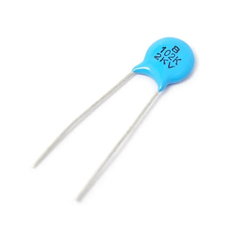
Figure 1: An IPUDIS High Voltage Ceramic Capacitor. This image shows a typical ceramic disc capacitor, characterized by its small size and disc shape, with two radial leads for connection.
2. Safety Information
Working with high voltage components can be hazardous. Adhere to the following safety guidelines:
- High Voltage Risk: These capacitors are rated for 2000V. Always ensure power is disconnected and circuits are fully discharged before handling.
- Proper Insulation: Use appropriate insulation tools and wear personal protective equipment (PPE) such as insulated gloves and safety glasses.
- Professional Installation: Installation should only be performed by qualified personnel with experience in high voltage electronics.
- Avoid Short Circuits: Prevent accidental short circuits during installation and operation.
- Environmental Conditions: Do not expose capacitors to excessive moisture, extreme temperatures, or corrosive environments.
3. Setup and Installation
Follow these steps for proper installation of the ceramic capacitors:
- Inspect Components: Before installation, visually inspect each capacitor for any physical damage, such as cracks, bent leads, or discoloration. Do not use damaged components.
- Prepare Circuit Board: Ensure the circuit board or application area is clean and free of debris. Identify the correct placement for the capacitor.
- Lead Forming (if necessary): Gently bend the leads to fit the mounting holes. Avoid sharp bends near the capacitor body to prevent stress on the ceramic material.
- Soldering: Solder the capacitor leads to the circuit board using appropriate soldering techniques. Use a soldering iron with controlled temperature to prevent overheating the component. Ensure good solder joints for reliable electrical connection.
- Clean Residue: After soldering, clean any flux residue from the board to prevent corrosion or electrical leakage.
- Verify Installation: Double-check all connections and ensure the capacitor is securely mounted and correctly oriented (if polarity is applicable, though ceramic capacitors are generally non-polarized).
4. Operating Principles
IPUDIS High Voltage Ceramic Capacitors are designed for various electronic applications, including:
- Filtering: Used to smooth out voltage fluctuations in power supplies.
- Coupling/Decoupling: Blocking DC current while allowing AC signals to pass, or shunting high-frequency noise to ground.
- Resonant Circuits: Forming part of LC circuits for frequency selection.
- Voltage Multipliers: Essential components in circuits that generate higher DC voltages from a lower AC input.
Ensure that the operating voltage and current in your circuit do not exceed the capacitor's rated specifications (2000V). Exceeding these limits can lead to component failure and potential safety hazards.
5. Maintenance
Ceramic capacitors are generally robust and require minimal maintenance. However, periodic inspection is recommended:
- Visual Inspection: Regularly check for any signs of physical damage, such as cracks, bulges, or discoloration, especially after prolonged operation or exposure to harsh conditions.
- Environmental Control: Maintain a stable operating environment within the specified temperature and humidity ranges to prolong component life.
- Cleaning: If necessary, gently clean the exterior of the capacitors and surrounding circuit board with a soft, dry brush or an electronics-safe cleaning solution. Ensure the circuit is powered off and discharged before cleaning.
6. Troubleshooting
If you encounter issues with your circuit involving these capacitors, consider the following:
- No Functionality:
- Check for proper soldering and connections.
- Verify correct component placement in the circuit.
- Ensure the capacitor is not damaged (e.g., cracked ceramic).
- Unexpected Circuit Behavior:
- Confirm the capacitor's value (1000PF/1nF) and voltage rating (2000V) match the circuit requirements.
- Measure capacitance with a multimeter if possible, ensuring it is within tolerance.
- Check for excessive ripple or noise, which might indicate a failing capacitor or an issue with other circuit components.
- Overheating:
- Ensure the capacitor is not subjected to voltages exceeding its rated 2000V.
- Verify that the operating frequency and current are within acceptable limits for ceramic capacitors.
- Check for short circuits elsewhere in the system that could cause excessive current draw through the capacitor.
If issues persist, consult a qualified electronics technician.
7. Specifications
The following are the key specifications for the IPUDIS High Voltage Ceramic Capacitor 102K 2KV/102 1000PF 1nF 2000V:
| Parameter | Value |
|---|---|
| Capacitance | 1000 PF (1 nF) |
| Voltage Rating | 2000 V (2KV) |
| Tolerance | 10% (K) |
| Type | Ceramic Disc Capacitor |
| Manufacturer | IPUDIS |
| Package Dimensions | Approximately 1.18 x 0.79 x 0.39 inches (based on general product dimensions) |
| Item Weight | Approximately 0.353 ounces (for the lot of 50) |
Note: Specifications are subject to change without notice. Always refer to the latest product datasheet for critical design parameters.
8. Warranty and Support
For warranty information and technical support regarding IPUDIS products, please refer to the vendor or retailer from whom the product was purchased. Keep your purchase receipt as proof of purchase.
For general inquiries or further assistance, you may attempt to contact the manufacturer, IPUDIS, through their official channels if available.