
1. Introduction
This manual provides essential instructions for the safe and effective operation, setup, maintenance, and troubleshooting of your agreilduite Portable Spot Welding Machine. Please read this manual thoroughly before using the device to ensure proper function and to prevent damage or injury.
2. Safety Information
WARNING: Improper use of welding equipment can cause serious injury or death. Always follow safety guidelines.
- Always wear appropriate personal protective equipment (PPE), including welding gloves and eye protection, when operating the machine.
- Ensure the work area is well-ventilated to avoid inhaling fumes.
- Do not operate the machine in damp or wet conditions.
- Keep children and unauthorized personnel away from the welding area.
- Disconnect power before performing any maintenance or changing accessories.
- Do not touch the welding pins or workpieces immediately after welding, as they will be hot.
- Ensure the power supply meets the machine's requirements (e.g., 12V power supply >3A).
3. Package Contents
Verify that all items listed below are present in your package:
- 1 x Electric Welding Machine
- 1 x Foot Pedal
- 1 x Spot Welding Pen (with cables)
- 4 x Welding Pins (replaceable)

Figure 3.1: All components included in the agreilduite Portable Spot Welding Machine package.
4. Product Overview
The agreilduite Portable Spot Welding Machine is a compact and efficient tool designed for battery pack assembly and other micro-welding applications. It features a 1.8-inch LCD for real-time data monitoring and a stepless adjustment knob for precise control.

Figure 4.1: Main unit of the Portable Spot Welding Machine.
4.1 Key Features
- 1.8-inch LCD Display: Provides real-time monitoring of welding parameters.
- Stepless Adjustment Knob: Allows fine-tuning of output current (1-25.0 range).
- Dual Mode Operation: Supports both automatic and foot pedal control.
- Capacitor-based Design: Utilizes a 1500F capacitance for stable and powerful welding.
- Welding Thickness: Capable of welding nickel strips from 0.1mm up to 0.3mm.
- Portable Design: Compact aluminum alloy casing with a handle for easy transport.

Figure 4.2: Key features and welding capabilities.
5. Setup
Follow these steps to set up your spot welding machine:
- Unpack: Carefully remove all components from the packaging.
- Connect Welding Pen: Insert the cables of the spot welding pen into the designated output ports on the front of the machine. Ensure a secure connection.
- Connect Foot Pedal (Optional): If using pedal control, connect the foot pedal to its dedicated port on the machine.
- Connect Power: Connect a compatible 12V power supply (minimum 3A, 5.5-2.1 plug adaptable) to the machine's power input port.
- Placement: Place the machine on a stable, non-flammable surface in a well-ventilated area.
6. Operating Instructions
6.1 Power On/Off
Once the power supply is connected, the machine will power on automatically, and the LCD will illuminate. To power off, disconnect the power supply.
6.2 LCD Display and Adjustment Knob
The 1.8-inch LCD displays real-time welding data, including capacitance voltage (C1, C2), welding time, delay, and temperature. The large knob on the front panel is used to adjust the output current.
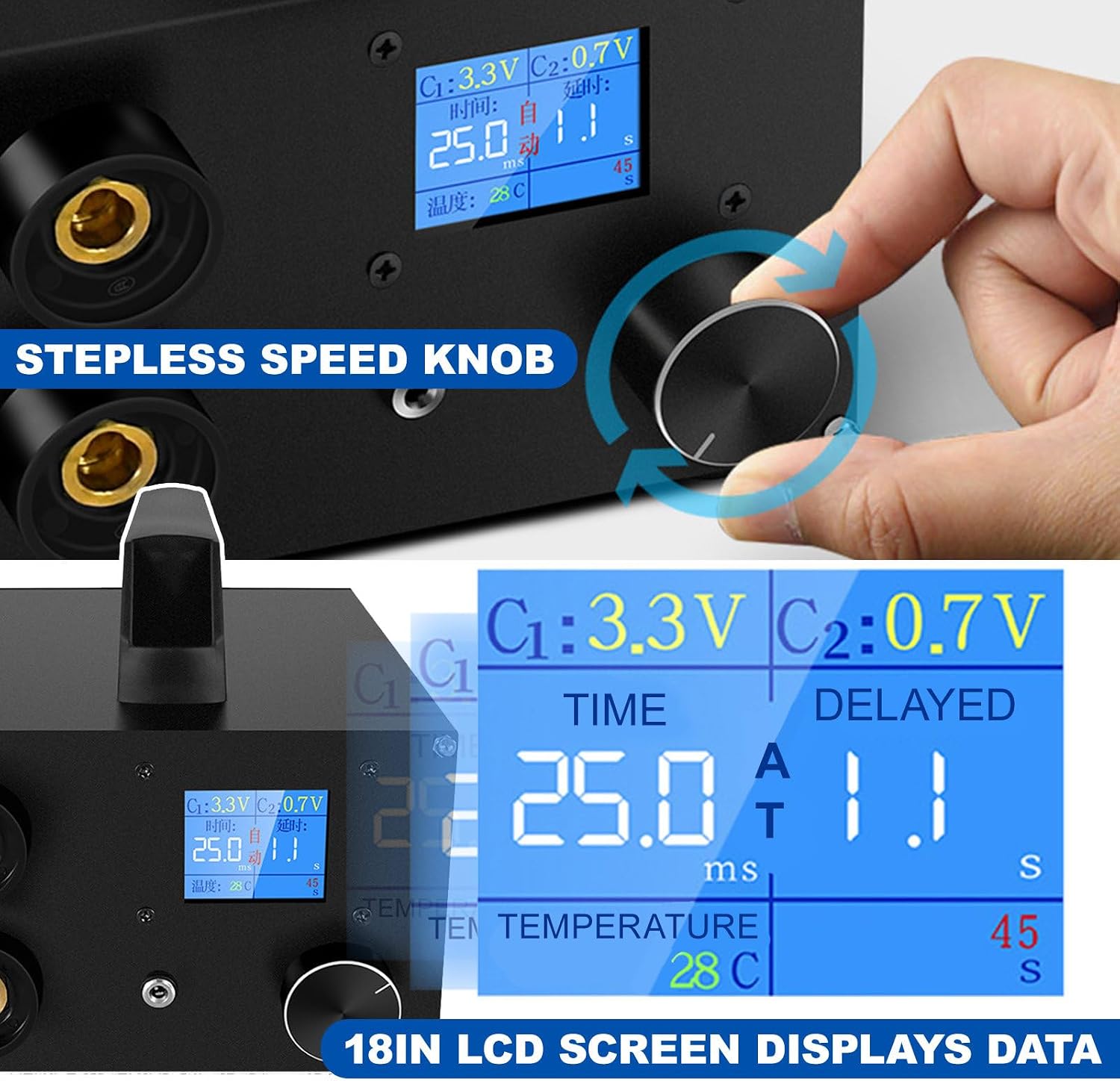
Figure 6.1: LCD display and stepless adjustment knob.
- Adjusting Output Current: Rotate the knob to increase or decrease the output current. The range is 1.0 to 25.0. A higher value indicates higher output. Adjust this setting based on the thickness and material of the nickel strip being welded.
- Precision: The adjustment is precise to 0.1 digit, allowing for fine-tuning to achieve optimal weld quality.
6.3 Welding Modes: Automatic & Pedal Control
The machine supports two operating modes:
- Automatic Mode: The machine automatically detects when the welding needle contacts the nickel strip and initiates the welding pulse.
- Pedal Control Mode: Welding is initiated by pressing the foot pedal. This provides manual control over the welding timing.
You can switch between these modes based on your preference and application requirements.
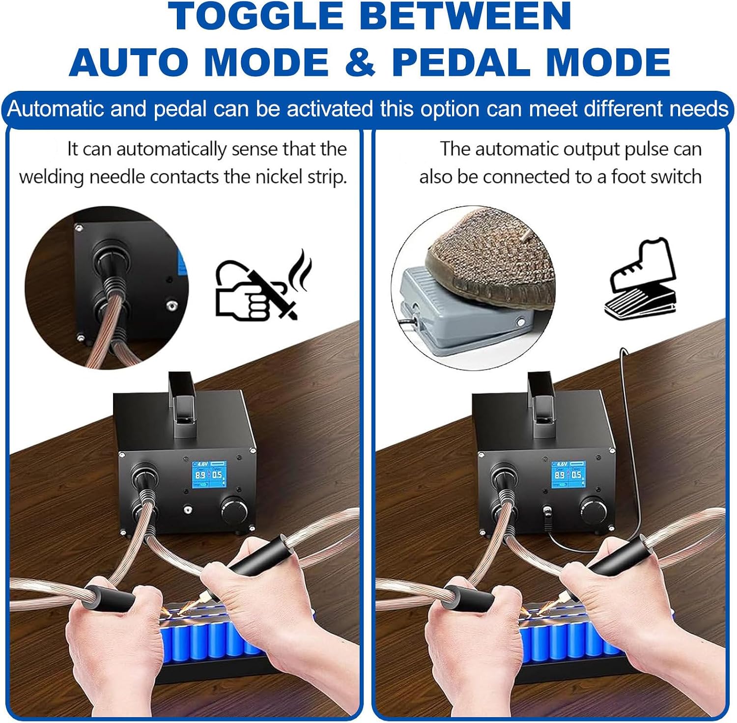
Figure 6.2: Automatic vs. Pedal Control welding modes.
6.4 Welding Process
- Prepare Workpiece: Ensure the nickel strip and battery terminals are clean and free of oxidation.
- Set Current: Adjust the output current using the knob according to the nickel strip thickness (e.g., 0.1mm to 0.3mm). Start with a lower setting and increase gradually if needed.
- Position: Place the nickel strip firmly against the battery terminal.
- Weld: Apply the welding pen tips to the nickel strip, ensuring good contact. If in automatic mode, the weld will trigger. If in pedal mode, press the foot pedal to initiate the weld.
- Inspect: After welding, inspect the joint for strength and appearance. Adjust settings if necessary.
7. Maintenance
7.1 Cleaning
- Regularly clean the welding pen tips to remove any residue.
- Wipe the machine's casing with a dry, soft cloth. Do not use abrasive cleaners or solvents.
7.2 Replacing Welding Pins
The welding pins are consumable parts and will wear down over time. Replace them when they become dull or pitted to ensure consistent weld quality.

Figure 7.1: Replaceable welding needles.
- Ensure the machine is powered off and disconnected from the power supply.
- Unscrew the worn welding pin from the welding pen.
- Screw in a new welding pin firmly.
8. Troubleshooting
- No Power: Check the power supply connection and ensure the 12V power adapter is functioning correctly.
- Weak Welds: Increase the output current setting. Ensure welding pins are clean and sharp. Verify good contact between the nickel strip and battery terminal.
- Overheating: Allow the machine to cool down. Ensure adequate ventilation around the unit. The machine has temperature control protection.
- Automatic Mode Not Triggering: Ensure the welding pins are making firm and simultaneous contact with the nickel strip.
- Foot Pedal Not Working: Check the foot pedal connection. Ensure the machine is in pedal control mode if applicable.
If problems persist, contact customer support.
9. Specifications
| Feature | Specification |
|---|---|
| Product Name | Digital Display Spot Welding Pen |
| Screen | 1.8 inch LCD |
| Peak Output Current | 1400A |
| Welding Thickness | 0.1-0.3mm (Nickel Strip) |
| Capacitance | 1500F |
| Casing Material | Aluminum Alloy |
| Control Modes | Automatic / Pedal Control |
| Output Current Adjustment | 1.0-25.0 (Stepless) |
| Power Supply Requirement | 12V >3A (5.5-2.1 plug adaptable) |
| Item Weight | 7.26 pounds (approx. 3.3 kg) |
| Package Dimensions | 9.84 x 8.27 x 7.87 inches |

Figure 9.1: Machine dimensions and portability.
10. Warranty and Support
For warranty information or technical support, please refer to the documentation provided with your purchase or contact the seller directly. Ensure you have your product model and purchase details available when seeking support.