Product Overview
The JOXLOVER G2BW Home Security Alarm System is a comprehensive security solution designed to protect your property. It integrates WiFi, GSM, and PSTN communication methods, offering versatile connectivity for alarm notifications. The system features an intuitive LCD keypad for easy operation, supporting both wireless and wired sensors to cover various security needs. It includes functionalities such as real-time arming/disarming, timing arm/disarm, and mobile application control for convenient management from anywhere.

Figure 1: Complete JOXLOVER G2BW Home Security Alarm System kit. This image displays the main control panel with LCD display and keypad, a red outdoor siren, a white panic button, a smoke detector, multiple wireless door/window sensors, wireless motion sensors, and remote controls.

Figure 2: System Diagram. This diagram illustrates how various components of the JOXLOVER G2BW system interact with the main control panel. It shows connections from door sensors, PIR motion sensors, 10kg pet PIR sensors, fire smoke detectors, and remote controls to the central unit. The diagram also depicts control methods via mobile phone app, calls, and SMS, and the output to a 120db siren.
Components
The G2BW system typically includes the following components. Specific bundles may vary.
- Main Control Panel with LCD Display and Keypad
- Wireless Motion Sensors (PIR)
- Wireless Door/Window Sensors
- Remote Controls
- Smoke Detector (depending on bundle)
- Wired Siren (depending on bundle)

Figure 3: Individual Component Details. This image provides a detailed look at individual components: a motion sensor with its detection window, a door sensor with a signal light and SOS button, and a remote control with labeled buttons for indicator light, arm, disarm, home arm, and SOS button.
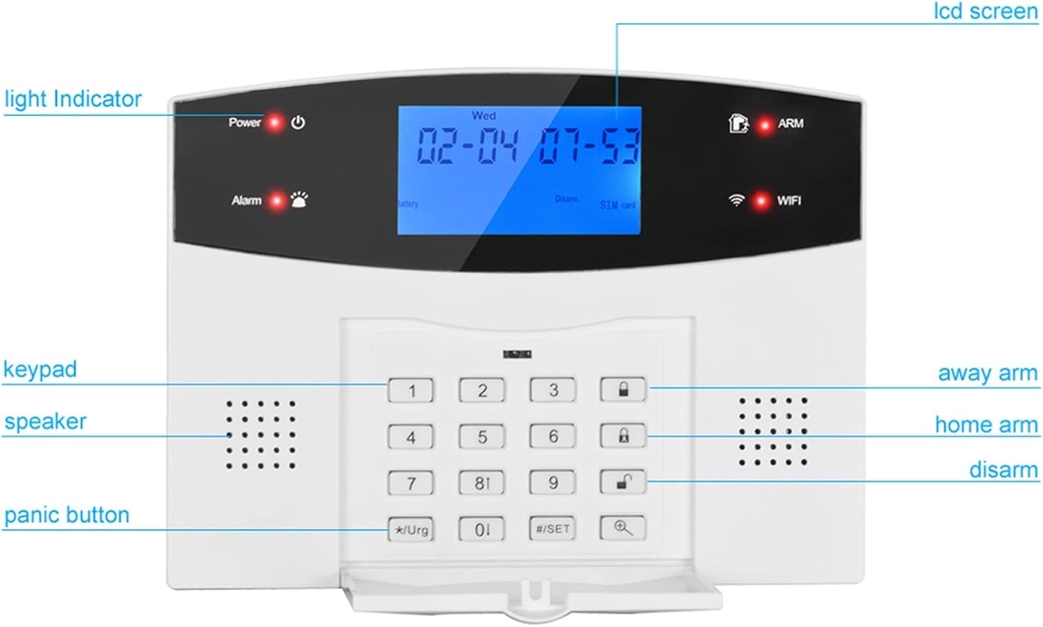
Figure 4: Main Control Panel Front View. A close-up of the JOXLOVER G2BW control panel's front, with labels pointing to key features: LCD screen, light indicator, keypad, speaker, panic button, and status indicators for power, alarm, battery, disarm, SIM card, ARM, and WiFi.

Figure 5: Main Control Panel Rear View. The rear view of the JOXLOVER G2BW control panel, showing its various connection ports and internal components. Labels indicate: 1. SIM card slot, 2. telephone line interface, 3. 12V power connector, 4. switch, 5. electronic box, 6. wired siren interface, 7. 4pcs wire zones interface, 8. relay output, 9. 12V voltage output.
Setup
1. Unpacking and Initial Inspection
Carefully unpack all components and verify that all items listed in your bundle are present and undamaged. Keep the packaging for future use or in case of return.
2. Main Panel Connections
Refer to Figure 5 for the location of ports on the rear of the control panel.
- Power Connection: Connect the provided 12V power adapter to the 12V power connector (3) on the back of the panel and plug it into a wall outlet. Ensure the power switch (4) is in the ON position.
- SIM Card Installation: If using GSM functionality, insert a valid SIM card into the SIM card slot (1). Ensure the SIM card is activated and has sufficient credit/data.
- Telephone Line Connection (PSTN): If using PSTN functionality, connect a telephone line to the telephone line interface (2).
- Wired Zone Connections: For wired sensors, connect them to the 4pcs wire zones interface (7). Follow the wiring diagram provided with your wired sensors.
- Wired Siren Connection: If using a wired siren, connect it to the wired siren interface (6).
3. Sensor Installation
Install batteries into all wireless sensors (motion sensors, door/window sensors, smoke detectors) according to their individual instructions. Ensure correct polarity.
- Motion Sensor Placement: Mount motion sensors in corners of rooms, approximately 2-2.5 meters (6.5-8 feet) high, ensuring a clear line of sight to the detection area. Avoid pointing them directly at heat sources or windows.
- Door/Window Sensor Placement: Install door/window sensors on the frame and the moving part of doors and windows. Ensure the two parts are aligned and within 1 cm (0.4 inches) of each other when the door/window is closed.
- Smoke Detector Placement: Install smoke detectors on ceilings or high on walls, away from vents or fans. Follow local fire safety guidelines for optimal placement.
4. System Pairing (Wireless Components)
To pair wireless sensors and remote controls with the main panel:
- Enter the system's programming mode (refer to the on-screen menu or specific instructions for your panel).
- Select the option to add wireless accessories or zones.
- Trigger each sensor (e.g., open a door with a door sensor, wave hand in front of a motion sensor, press a button on the remote control). The panel will register the new device.
- Assign each sensor to a specific zone and name it (e.g., "Front Door," "Living Room PIR"). The zone name can be modified by users.
5. Network Configuration (WiFi/GSM/PSTN)
- WiFi Setup: Navigate to the WiFi settings on the LCD panel. Select your home WiFi network and enter the password. Ensure a stable internet connection for app push notifications.
- GSM/PSTN Setup: Program the alarm call numbers (up to 4 groups) and SMS notification numbers (up to 3 groups) into the system via the keypad menu. These numbers will receive alerts when an alarm is triggered.
Operating Instructions
1. Keypad Functions
The LCD keypad allows for direct control and programming of the system. Common buttons include:
- Number Keys (0-9): For entering codes and navigating menus.
- Arm/Away Arm: Activates all sensors for full protection when leaving the property.
- Home Arm: Activates perimeter sensors (e.g., door/window sensors) while allowing movement inside.
- Disarm: Deactivates the alarm system. Requires your security code.
- Panic Button (*Urgent): Triggers an immediate alarm.
- Set (#SET): Enters programming mode or confirms selections.
2. Arming and Disarming
- To Arm (Away): Enter your security code, then press the "Arm" or "Away Arm" button. The system will provide an exit delay.
- To Arm (Home): Enter your security code, then press the "Home Arm" button.
- To Disarm: Enter your security code, then press the "Disarm" button. This will silence any active alarms and deactivate the system.
- Timing Arm/Disarm: The system supports scheduled arming and disarming. Configure these times through the system's menu settings.
3. Zone Management
The system supports 99 wireless zones and 4 wired zones. Each zone can be configured for different types of sensors (e.g., entry/exit, 24-hour, home arm bypass). You can customize zone names for easier identification.
4. Mobile App Control
Download the official mobile application (check the product packaging or manual for the app name/QR code). The app allows you to:
- Arm and Disarm the system remotely.
- Receive real-time alarm push notifications.
- View system status (e.g., battery low, WiFi disconnected).
- Manage zones and settings.
- View IP camera feeds (if integrated).
5. Voice Message Recording
The system allows for a 10-second voice message recording. This message can be played back when an alarm call is made, providing additional information to the recipient. Refer to the system menu for recording instructions.
6. Alarm Notifications
Upon an alarm trigger, the system will initiate notifications based on your configuration:
- App Push Notifications: Instant alerts sent to your mobile application via WiFi.
- SMS Notifications: Text messages sent to programmed phone numbers via GSM.
- Phone Calls: Automated calls made to programmed phone numbers via GSM or PSTN, playing the recorded voice message.
- Siren: The optional siren will sound, with adjustable sounding time.
The system will also notify you of low panel battery, WiFi disconnection, or AC power disconnection.
Maintenance
1. Battery Replacement
The system will alert you when sensor batteries are low. Replace batteries promptly to ensure continuous protection. Refer to individual sensor manuals for specific battery types and replacement procedures.
- Wireless Sensors: Typically use standard AAA, AA, or button cell batteries.
- Main Panel: The main panel has a built-in backup battery. If the panel indicates a low battery, contact support for replacement or follow specific instructions in the full manual if user-replaceable.
2. Cleaning
Clean the control panel and sensors periodically with a soft, dry cloth. Do not use abrasive cleaners, solvents, or spray liquids directly onto the devices. Keep sensors free from dust and debris to ensure proper operation.
3. System Updates
Check the mobile application or manufacturer's website for any available firmware updates for your system. Updates can improve performance, add new features, or address security vulnerabilities.
Troubleshooting
If you encounter issues with your JOXLOVER G2BW system, refer to the table below for common problems and solutions.
| Problem | Possible Cause | Solution |
|---|---|---|
| System not arming | An open zone (door/window), sensor fault. | Check the LCD display for open zones and ensure all doors/windows are closed. Verify sensor functionality. |
| False alarms | Improper sensor placement, pet interference (for standard PIR), strong air currents. | Adjust sensor sensitivity or reposition. Consider using pet-immune PIR sensors if you have pets. Ensure sensors are not near vents or direct sunlight. |
| No alarm notifications (App/SMS/Call) | No WiFi connection, no GSM signal, incorrect programmed phone numbers, SIM card issues. | Check WiFi status on the panel. Ensure SIM card is properly inserted and has credit/signal. Verify programmed alarm numbers in system settings. |
| Keypad unresponsive | Power issue, system freeze. | Check power connection. Try restarting the system by unplugging and replugging the power adapter (ensure backup battery is also disconnected if possible, then reconnect). |
| Low battery alerts for sensors | Sensor battery is depleted. | Replace the batteries in the affected sensors immediately. |
If the problem persists after attempting these solutions, please contact customer support.
Specifications
- Model: G2BW
- Brand: JOXLOVER
- Communication Modes: WiFi, GSM, PSTN
- Display: LCD Screen
- Wireless Zones: 99
- Wired Zones: 4
- Relay Output: 1
- Voltage Output: 12V
- Voice Recording: 10 seconds
- Alarm Phone Numbers: 4 groups
- SMS Phone Numbers: 3 groups
- Control: Keypad, Remote Control, Mobile Application

Figure 6: Key System Capabilities. This image visually summarizes the main control panel's communication capabilities (WiFi, GSM, PSTN) and system capacity, including 99 wireless zones, 4 wired zones, 1 relay output, and 12V voltage output.
Warranty and Support
Warranty information for the JOXLOVER G2BW Home Security Alarm System is typically provided at the point of purchase or within the product packaging. Please retain your proof of purchase for warranty claims.
For technical support, troubleshooting assistance beyond this manual, or warranty inquiries, please contact your retailer or the manufacturer directly. Contact details can usually be found on the product packaging or the seller's information page.
It is recommended to seek professional assistance if you encounter complex installation issues or system malfunctions that cannot be resolved using this manual.