1. Introduction
This manual provides essential information for the safe and effective operation of your THEMISTO TH-M200 True RMS Digital Multimeter. Please read this manual thoroughly before using the device to ensure proper function and to prevent potential hazards. The TH-M200 is a versatile, auto-ranging digital multimeter designed for measuring AC/DC voltage, AC/DC current, resistance, capacitance, frequency, temperature, continuity, and diode testing. It features True RMS measurement for accurate readings and a 9999-count display.

Image 1.1: THEMISTO TH-M200 Digital Multimeter, including test leads and a protective carrying case.
2. Safety Information
WARNING: To avoid electric shock or personal injury, read all safety information before using this product.
- Always ensure the multimeter is in the correct function mode and range before making measurements.
- Do not apply more than the rated voltage, as marked on the multimeter, between the terminals or between any terminal and earth ground.
- Use caution when working with voltages above 30V AC RMS, 42V peak, or 60V DC. These voltages pose a shock hazard.
- Inspect test leads for damaged insulation or exposed metal before use. Replace damaged leads immediately.
- Do not operate the multimeter if it appears damaged or if the case is open.
- Remove test leads from the circuit before changing functions.
- Replace the battery and fuses only with the specified type and rating.
- Adhere to local and national safety codes.
3. Product Overview and Components
The THEMISTO TH-M200 Digital Multimeter is designed for ease of use and clear readings. Familiarize yourself with its main components:
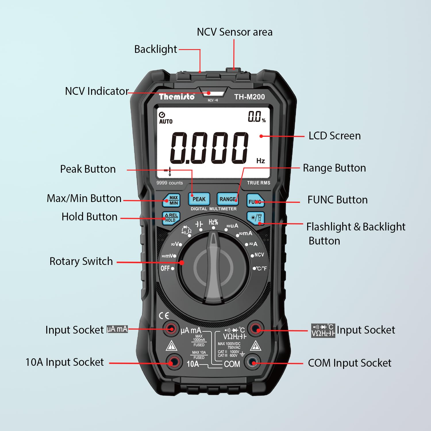
Image 3.1: Front panel layout of the THEMISTO TH-M200 Multimeter with key components labeled.
- NCV Sensor Area: Detects non-contact voltage.
- NCV Indicator: Lights up when non-contact voltage is detected.
- LCD Screen: Displays measurement readings, units, and function indicators. Features a backlight for low-light conditions.
- Peak Button: Captures peak values.
- Max/Min Button: Records maximum and minimum readings.
- ΔREL Hold Button: Data hold and relative measurement function.
- Rotary Switch: Selects measurement functions (OFF, V~, V=, mV~, mV=, μA~, μA=, mA~, mA=, A~, A=, Ω, ⟘, NCV, °C/°F).
- Input Socket (μA mA): For microampere and milliampere current measurements.
- 10A Input Socket: For high current (up to 10A) measurements.
- COM Input Socket: Common terminal for all measurements (negative lead).
- VΩHz+ Input Socket: For voltage, resistance, frequency, capacitance, diode, and continuity measurements (positive lead).
- Range Button: Manually selects measurement range (in manual ranging modes).
- FUNC Button: Toggles between functions within a single rotary switch position (e.g., AC/DC voltage, diode/continuity).
- Flashlight & Backlight Button: Activates the flashlight and LCD backlight.
4. Setup
4.1. Battery Installation
The TH-M200 requires 3 AAA batteries (included). To install or replace batteries:
- Ensure the multimeter is turned OFF and disconnect all test leads.
- Locate the battery compartment cover on the back of the device.
- Unscrew the retaining screw(s) and remove the cover.
- Insert the 3 AAA batteries, observing correct polarity (+ and -).
- Replace the battery compartment cover and secure it with the screw(s).
4.2. Test Lead Connection
Connect the test leads to the appropriate input sockets:
- Insert the black test lead into the COM (Common) input socket.
- For most measurements (voltage, resistance, capacitance, frequency, diode, continuity, temperature), insert the red test lead into the VΩHz+ input socket.
- For current measurements up to 600mA, insert the red test lead into the μA mA input socket.
- For current measurements up to 10A, insert the red test lead into the 10A input socket.
CAUTION: Incorrect connection of test leads can damage the multimeter or the circuit under test.
5. Operating Instructions
The TH-M200 features an auto-ranging function for most measurements, simplifying operation. Use the rotary switch to select the desired measurement function.

Image 5.1: Overview of the versatile measurement functions available on the THEMISTO TH-M200.
5.1. AC/DC Voltage Measurement (V~, V=, mV~, mV=)
- Set the rotary switch to V~ (AC Voltage) or V= (DC Voltage) or mV~/mV= for millivolt measurements.
- Connect the red test lead to the VΩHz+ socket and the black test lead to the COM socket.
- Connect the test probes in parallel across the component or circuit to be measured.
- Read the voltage value on the LCD screen.
5.2. AC/DC Current Measurement (μA~, μA=, mA~, mA=, A~, A=)
WARNING: Never connect the multimeter in parallel to a voltage source when measuring current. This can blow the fuse or damage the meter.
- Set the rotary switch to the appropriate current range (μA, mA, or A) and type (AC~ or DC=).
- Connect the black test lead to the COM socket.
- Connect the red test lead to the μA mA socket for microampere/milliampere measurements, or to the 10A socket for ampere measurements.
- Open the circuit where current is to be measured and connect the multimeter in series with the circuit.
- Read the current value on the LCD screen.
5.3. Resistance Measurement (Ω)
- Set the rotary switch to Ω.
- Connect the red test lead to the VΩHz+ socket and the black test lead to the COM socket.
- Ensure the circuit or component is de-energized before measuring resistance.
- Connect the test probes across the component.
- Read the resistance value on the LCD screen.
5.4. Continuity Test (⟘)
- Set the rotary switch to Ω. Press the FUNC button to cycle to the continuity mode (indicated by a speaker icon).
- Connect the red test lead to the VΩHz+ socket and the black test lead to the COM socket.
- Ensure the circuit is de-energized.
- Connect the test probes across the circuit path. A continuous beep indicates a low-resistance path (continuity).
5.5. Diode Test (⟘)
- Set the rotary switch to Ω. Press the FUNC button to cycle to the diode mode (indicated by a diode symbol).
- Connect the red test lead to the VΩHz+ socket and the black test lead to the COM socket.
- Connect the red probe to the anode and the black probe to the cathode of the diode. A forward voltage drop (e.g., 0.5V to 0.8V for silicon diodes) will be displayed.
- Reverse the probes. An "OL" (Overload) reading indicates a good diode.
5.6. Capacitance Measurement
- Set the rotary switch to Ω. Press the FUNC button to cycle to the capacitance mode (indicated by a capacitor symbol).
- Connect the red test lead to the VΩHz+ socket and the black test lead to the COM socket.
- Ensure the capacitor is fully discharged before measurement to prevent damage to the meter.
- Connect the test probes across the capacitor terminals.
- Read the capacitance value on the LCD screen.
5.7. Frequency Measurement (Hz)
- Set the rotary switch to Hz.
- Connect the red test lead to the VΩHz+ socket and the black test lead to the COM socket.
- Connect the test probes in parallel across the signal source.
- Read the frequency value on the LCD screen.
5.8. Temperature Measurement (°C/°F)

Image 5.8.1: Temperature measurement using the THEMISTO TH-M200 with a thermocouple.
- Set the rotary switch to °C/°F.
- Connect the temperature probe (K-type thermocouple, usually included) to the VΩHz+ and COM sockets, observing polarity.
- Place the tip of the temperature probe on or in the object to be measured.
- Read the temperature value on the LCD screen. Press FUNC to switch between Celsius and Fahrenheit.
5.9. Non-Contact Voltage (NCV) Detection

Image 5.9.1: NCV detection in progress, showing the multimeter near an electrical outlet.
- Set the rotary switch to NCV.
- Move the NCV sensor area (top of the multimeter) close to the conductor or outlet.
- The NCV indicator will light up, and an audible alarm will sound, indicating the presence of AC voltage. The intensity of the alarm and indicator may vary with voltage strength.
5.10. Data Hold (ΔREL Hold Button)
- During any measurement, press the ΔREL Hold button briefly to freeze the current reading on the display. "HOLD" will appear on the screen.
- Press the button again to release the hold and resume live measurements.
5.11. Relative Measurement (ΔREL Hold Button)
- In a measurement mode, press and hold the ΔREL Hold button to activate relative measurement. The current reading becomes the reference value, and subsequent measurements are displayed as the difference from this reference. "REL" will appear on the screen.
- Press and hold the button again to exit relative measurement mode.
5.12. Backlight and Flashlight

Image 5.12.1: The TH-M200's backlit LCD and integrated flashlight for enhanced visibility.
- Press the Flashlight & Backlight button briefly to turn on the LCD backlight. Press again to turn it off.
- Press and hold the Flashlight & Backlight button to turn on the integrated flashlight. Press and hold again to turn it off.
6. Maintenance
6.1. Cleaning
Wipe the case with a damp cloth and mild detergent. Do not use abrasives or solvents. Ensure the device is completely dry before use.
6.2. Battery Replacement
When the battery indicator appears on the LCD, replace the batteries as described in Section 4.1. Prompt replacement ensures accurate readings.
6.3. Fuse Replacement
If the multimeter fails to measure current, the fuse may be blown. To replace a fuse:
- Ensure the multimeter is turned OFF and disconnect all test leads.
- Remove the protective rubber jacket.
- Unscrew the screws on the back cover and carefully open the case.
- Locate the blown fuse(s) and replace them with fuses of the exact same type and rating. The TH-M200 typically uses two fuses:
- F1: 600mA/250V Fast-acting fuse (for μA/mA range)
- F2: 10A/250V Fast-acting fuse (for 10A range)
- Carefully close the case, secure the screws, and reattach the rubber jacket.
WARNING: Always use fuses with the specified voltage and current ratings to prevent fire or damage to the multimeter.
6.4. Storage
If the multimeter is not used for an extended period, remove the batteries to prevent leakage and damage. Store the device in a cool, dry place, away from direct sunlight and extreme temperatures.
7. Troubleshooting
| Problem | Possible Cause | Solution |
|---|---|---|
| No display or dim display | Dead or low batteries | Replace batteries (refer to Section 4.1). |
| "OL" (Overload) displayed | Measurement exceeds selected range or meter's maximum capacity. Open circuit (for continuity/current). | Switch to a higher range (if applicable). Ensure proper circuit connection. |
| Incorrect current reading | Blown fuse for the current range. Incorrect test lead connection. | Check and replace fuse (refer to Section 6.3). Verify test lead connection (refer to Section 4.2). |
| No continuity beep | Open circuit. Meter not in continuity mode. | Ensure circuit is closed. Select continuity mode using the FUNC button. |
| Inaccurate readings | Low battery. Environmental interference. Damaged test leads. | Replace batteries. Move away from strong electromagnetic fields. Inspect and replace test leads if damaged. |
8. Specifications
The following table outlines the general specifications for the THEMISTO TH-M200 Digital Multimeter:
| Feature | Detail |
|---|---|
| Model | TH-M200 |
| Display | 9999 Counts, Large Backlit LCD |
| Ranging | Auto-ranging |
| True RMS | Yes |
| AC Voltage | Up to 750V |
| DC Voltage | Up to 1000V |
| AC Current | Up to 10A |
| DC Current | Up to 10A |
| Resistance | Up to 100MΩ |
| Capacitance | Up to 100mF |
| Frequency | Up to 10MHz |
| Temperature | -20°C to +1000°C (-4°F to 1832°F) |
| Continuity Test | Yes, with buzzer |
| Diode Test | Yes |
| NCV (Non-Contact Voltage) | Yes |
| Data Hold | Yes |
| Flashlight | Yes |
| Power Source | 3 x AAA Batteries (included) |
| Auto Power Off | Yes (typically after 15 minutes of inactivity) |
| Dimensions (L x W x H) | 18.5 x 9 x 5 cm |
| Weight | 332 g |
| Safety Rating | CE, CAT III 1000V, CAT IV 600V |

Image 8.1: Model comparison highlighting the specifications of the TH-M200 against other Themisto multimeters.
9. Warranty and Support
9.1. Warranty Information
The THEMISTO TH-M200 Digital Multimeter comes with a 6-month warranty against manufacturing defects from the date of purchase. This warranty covers defects in materials and workmanship under normal use. It does not cover damage caused by misuse, accident, unauthorized modification, neglect, or improper operation.
9.2. Customer Support
For technical assistance, warranty claims, or any questions regarding your THEMISTO TH-M200 multimeter, please contact your retailer or the manufacturer's customer service. Refer to your purchase documentation for specific contact details.


