1. Product Overview
The Akozon MPS-V-PLUS-5.5KW Solar MPPT Pure Sine Wave Inverter is a versatile device designed to provide uninterrupted power. It integrates the functions of a solar inverter, solar charger, and battery charger into a single, portable unit. This inverter is compatible with both mains voltage and generator power, making it suitable for various household and office applications.

Figure 1: Front view of the Akozon MPS-V-PLUS-5.5KW Solar Inverter, showing the main casing and LCD display.

Figure 2: Side view of the Akozon MPS-V-PLUS-5.5KW Solar Inverter, highlighting the ventilation and communication port.
Key features include:
- Easy Operation: Equipped with an LCD screen for convenient adjustment of battery charging current, AC charger priority, and solar charger priority.
- Safety Features: Includes overload protection, short-circuit protection, and a cold start function, ensuring safe operation even without a connected battery.
- Flexible Charging Modes: Supports multiple charging modes to optimize battery performance: Utility First, Solar First, Solar and Utility, and Battery and Solar.
- Wide Compatibility: Designed to connect with various household and office loads, providing reliable power.
2. Safety Information
Please read all instructions and warnings carefully before installation and operation. Failure to follow these instructions may result in electric shock, fire, or severe injury.
- Ensure all wiring is performed by qualified personnel in accordance with local electrical codes.
- Do not disassemble the inverter. There are no user-serviceable parts inside. Refer all servicing to qualified service personnel.
- Install the inverter in a well-ventilated area, away from flammable materials and direct sunlight.
- Ensure proper grounding of the unit.
- Before connecting or disconnecting any wiring, ensure the inverter is turned off and disconnected from all power sources (AC, DC, and battery).
- Avoid touching live terminals.

Figure 3: Caution label on the inverter, indicating potential energy hazards. Always observe safety warnings.
3. Product Components and Connections
Familiarize yourself with the various components and connection points of your inverter. Refer to the diagram below for a detailed overview.

Figure 4: Detailed diagram showing the various components and connection ports of the inverter.
- LCD display
- Status indicator
- Charging indicator
- Fault indicator
- Function buttons (ENTER, UP, DOWN, ESC)
- Power on/off switch
- AC input
- AC output
- PV input (Solar Panel Input)
- Battery input
- Circuit breaker
- USB communication port
- RS-232 communication port

Figure 5: Close-up view of the power on/off switch located on the inverter.
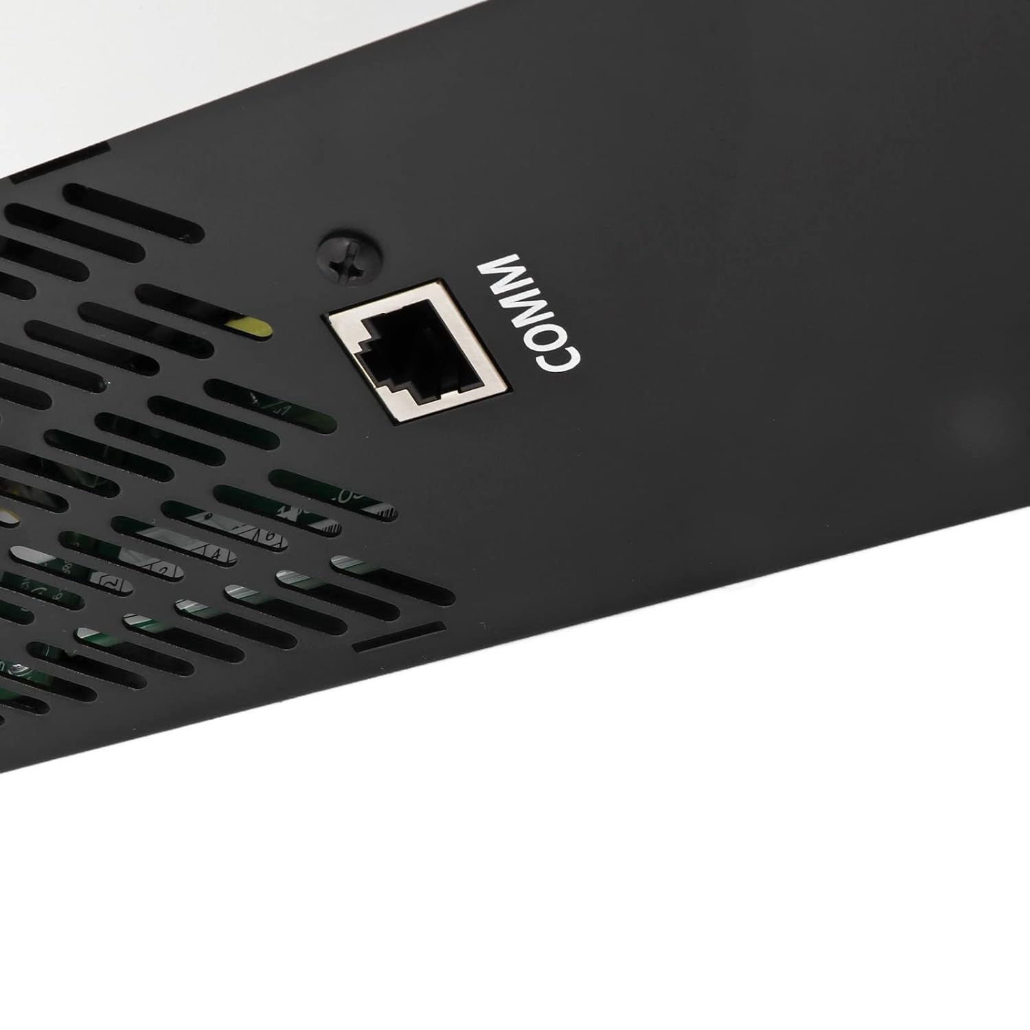
Figure 6: Close-up view of the COMM (communication) port, likely for USB or RS-232 connections.
4. Setup and Installation
Proper installation is crucial for the safe and efficient operation of your inverter. Follow these general steps. For detailed wiring diagrams, consult a qualified electrician.
- Mounting: Choose a suitable location for mounting the inverter. Ensure it is a dry, well-ventilated area, protected from direct sunlight, high temperatures, and moisture. Allow sufficient clearance around the unit for airflow.
- Battery Connection: Connect the battery bank to the Battery Input terminals (10) on the inverter. Ensure correct polarity (+ to + and - to -). Use appropriate gauge wiring for the current draw. The MPS-V-PLUS-5.5KW model requires a 48V DC input.
- Solar Panel (PV) Connection: Connect your solar panel array to the PV Input terminals (9). Observe the specified MPPT voltage range (120-450 VDC) and maximum open circuit voltage (500 VDC) to avoid damage.
- AC Input Connection: Connect the AC power source (grid or generator) to the AC Input terminals (7). This allows the inverter to charge batteries and/or pass through AC power.
- AC Output Connection: Connect your household or office loads to the AC Output terminals (8). Ensure the total load does not exceed the inverter's rated power (5500W).
- Grounding: Ensure the inverter is properly grounded according to local electrical codes.
- Initial Power-Up: Before turning on the inverter, double-check all connections for tightness and correct polarity. Then, switch on the circuit breaker (11) and the power on/off switch (6).
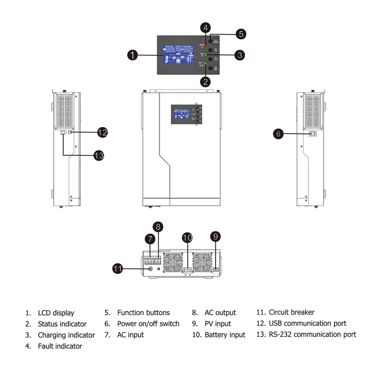
Figure 7: Example application diagram showing how the inverter can be integrated into various power systems, including rooftop solar, carports, RVs, and general household use.
5. Operating Instructions
The inverter features an intuitive LCD display (1) and function buttons (5) for easy configuration and monitoring.
- LCD Display: The LCD screen provides real-time information on system status, input/output voltages, battery charge level, and operational modes.
- Function Buttons: Use the ENTER, UP, DOWN, and ESC buttons to navigate through menus and adjust settings.
- ENTER: Confirms selection or enters a submenu.
- UP/DOWN: Navigates through menu options or adjusts values.
- ESC: Exits a submenu or cancels an operation.
- Setting Charging Current: Adjust the battery charging current via the LCD menu to match your battery bank's specifications.
- Setting Charger Priority: Configure the priority for AC charger and solar charger based on your energy management strategy (e.g., Solar First to maximize solar energy use).
- Operational Modes: The inverter supports various operational modes to optimize power flow:
- Utility First: Prioritizes grid power, using solar/battery only when the grid is unavailable.
- Solar First: Prioritizes solar power, using grid/battery as backup.
- Solar and Utility: Uses both solar and grid power simultaneously.
- Battery and Solar: Uses battery power primarily, supplemented by solar.

Figure 8: Front panel of the inverter, showing the LCD display and control buttons for operation and settings adjustment.
6. Maintenance
Regular maintenance helps ensure the longevity and optimal performance of your inverter.
- Cleaning: Periodically clean the exterior of the inverter with a soft, dry cloth. Ensure ventilation openings are free from dust and debris to prevent overheating.
- Connections: Annually check all electrical connections (battery, solar, AC input/output) for tightness. Loose connections can cause overheating and poor performance.
- Battery Health: If using lead-acid batteries, regularly check their water levels and terminal cleanliness. Follow the battery manufacturer's maintenance guidelines.
- Environment: Ensure the installation environment remains within the recommended temperature and humidity ranges.
7. Troubleshooting
This section provides basic troubleshooting steps for common issues. For more complex problems, contact technical support.
| Problem | Possible Cause | Solution |
|---|---|---|
| Inverter not turning on | No DC input from battery; Power switch off; Circuit breaker tripped. | Check battery connections and voltage; Ensure power switch (6) is ON; Reset circuit breaker (11). |
| No AC output | Overload; Short circuit; Battery low; Inverter in fault mode. | Reduce load; Check for short circuits in wiring; Charge battery; Check fault indicator (4) and LCD for error codes. |
| Battery not charging | Solar panels not connected/producing; AC input not present; Charging settings incorrect. | Check PV input (9) and solar panel output; Verify AC input (7); Adjust charging current and priority settings via LCD. |
| Fault indicator (4) is lit | Internal fault; Overload; Over-temperature. | Refer to LCD display for specific error code; Turn off inverter, wait 5 minutes, then restart; Ensure proper ventilation. If fault persists, contact support. |
8. Specifications
Technical specifications for the Akozon MPS-V-PLUS-5.5KW Solar MPPT Pure Sine Wave Inverter.
| Parameter | Value (MPS-V-PLUS-5.5KW) |
|---|---|
| Inverter Mode | |
| Rated Power | 5500 W |
| DC Input | 48 VDC |
| AC Output | 230 VAC, 50/60 Hz, 15.2 A, 1Φ |
| AC Charger Mode | |
| AC Input | 230 VAC, 50/60 Hz, 24.9 A, 1Φ |
| DC Output (Charging) | 27 VDC, max 80 A (30 A default) |
| AC Output (Bypass) | 230 VAC, 50/60 Hz, 15.2 A, 1Φ |
| Solar Charger Mode | |
| Rated Power | 5000 W |
| Maximum Charger Current | 100 A |
| Rated Operating Voltage | 240 VDC |
| Maximum Solar VOC (Open Circuit Voltage) | 500 VDC |
| MPPT Voltage Range | 120-450 VDC |
| General Information | |
| Manufacturer Model Number | Akozon6r5aok0uze-12 |
| Package Dimensions | 60 x 40 x 21 cm |
| Item Weight | 10.75 kg |
| Country of Origin | China |
9. Warranty and Support
Information regarding specific warranty terms for this product was not provided in the product data. For warranty claims or technical support, please contact your retailer or the manufacturer, Akozon, directly.
Spare parts availability information is currently unavailable.