1. Introduction
The JDOUNFMO GD112B is an intelligent True RMS digital clamp meter designed for comprehensive electrical measurements. This device integrates intelligent identification and manual function selection to measure AC and DC voltage, AC and DC current, resistance, capacitance, continuity, diode, Non-Contact Voltage (NCV), frequency, duty cycle, and temperature. It is an essential tool for professional electricians, engineers, electronic enthusiasts, and for general household electrical testing.

Image 1.1: The JDOUNFMO GD112B Digital Clamp Meter with its included test leads. This image shows the main unit, the clamp jaw, the rotary dial, LCD display, and the red and black test probes.
2. Safety Information
Please read and understand all safety information before operating this device. Failure to follow these instructions may result in electric shock, fire, or damage to the meter.
- Always ensure the meter is in the correct function and range for the measurement being performed.
- Do not exceed the maximum input values for any range.
- Inspect test leads for damaged insulation or exposed metal before use. Replace if damaged.
- Do not use the meter if it appears damaged or if the case is open.
- Exercise extreme caution when working with voltages above 60V DC or 30V AC RMS, as these pose a shock hazard.
- When measuring current, ensure the circuit is de-energized before clamping the jaw around the conductor.
- High Voltage/Current Warning: The LCD backlight will turn orange to warn the user when current exceeds 3A or voltage exceeds 80V, indicating a potentially dangerous condition.
- Remove test leads from the circuit before changing functions or ranges.
- Replace batteries immediately when the low battery indicator appears to ensure accurate readings.
3. Product Features
The JDOUNFMO GD112B offers a range of features for versatile electrical testing:
- Maximum Display: 6000 Counts for high-resolution readings.
- True RMS: Accurate measurements for non-sinusoidal waveforms.
- Measurement Functions: AC/DC Voltage, AC/DC Current, Resistance, Capacitance, Frequency, Duty Cycle, Temperature.
- Non-Contact Voltage (NCV) Detection: For identifying live wires without direct contact, featuring a 26mm jaw design.
- Continuity and Diode Test: For checking circuit integrity and diode functionality.
- Automatic Power Off: Conserves battery life.
- Data Hold: Freezes the displayed reading for easy recording.
- MAX/MIN Function: Records maximum and minimum values during a measurement.
- Double Backlight Warning: Orange backlight illuminates when current exceeds 3A or voltage exceeds 80V.
- Built-in LED Flashlight: For illumination in dimly lit work areas.
- LowZ (Low Impedance) Function: Helps eliminate ghost voltages.
- LPF (Low Pass Filter) Function: For accurate measurements on variable frequency drives.
4. Setup
4.1 Battery Installation
The GD112B requires two 1.5V AAA batteries for operation. To install or replace batteries:
- Ensure the meter is turned OFF and disconnect all test leads from the meter and any circuits.
- Locate the battery compartment cover on the back of the meter.
- Use a screwdriver to loosen the screw on the battery compartment cover.
- Remove the cover and insert two 1.5V AAA batteries, observing the correct polarity (+ and -).
- Replace the battery compartment cover and tighten the screw securely.

Image 4.1: Rear view of the GD112B showing the battery compartment with two AAA batteries and the cover removed. This illustrates how to install the batteries.
4.2 Connecting Test Leads
For most voltage, resistance, capacitance, continuity, and diode measurements, connect the test leads as follows:
- Insert the red test lead into the VΩHzCAP input jack.
- Insert the black test lead into the COM (common) input jack.
Ensure the connections are firm before taking any measurements.
5. Operating Instructions
This section details how to use the JDOUNFMO GD112B for various measurement functions.
5.1 Power On/Off and Function Selection
To power on the meter, rotate the rotary dial from the 'OFF' position to the desired measurement function. To power off, rotate the dial back to 'OFF'.
5.2 Measuring AC/DC Voltage
- Connect the test leads as described in Section 4.2.
- Rotate the dial to the V~ (AC Voltage) or V- (DC Voltage) position. The meter will automatically select the range.
- Touch the test probes to the circuit points where voltage is to be measured (in parallel with the load).
- Read the voltage value on the LCD display.
5.3 Measuring AC/DC Current (Clamp Function)
The clamp function is used for non-contact current measurement.
- Rotate the dial to the 600A (AC Current) or 600A (DC Current) position. Use the 'FUNC' button to switch between AC and DC current if needed.
- Press the jaw trigger to open the clamp jaw.
- Enclose only one conductor of the circuit within the clamp jaw. Ensure the jaw is fully closed.
- Read the current value on the LCD display.
5.4 Measuring Resistance (Ω)
- Ensure the circuit is de-energized before measuring resistance.
- Connect the test leads as described in Section 4.2.
- Rotate the dial to the Ω position.
- Touch the test probes across the component or circuit segment to be measured.
- Read the resistance value on the LCD display.
5.5 Measuring Capacitance (CAP)
- Ensure the capacitor is fully discharged before measurement to prevent damage to the meter.
- Connect the test leads as described in Section 4.2.
- Rotate the dial to the CAP position.
- Touch the test probes across the capacitor terminals.
- Read the capacitance value on the LCD display.
5.6 Measuring Frequency (Hz) / Duty Cycle (%)
- Connect the test leads as described in Section 4.2.
- Rotate the dial to the Hz% position.
- Use the 'FUNC' button to toggle between Frequency (Hz) and Duty Cycle (%).
- Touch the test probes to the signal source.
- Read the frequency or duty cycle value on the LCD display.
5.7 Temperature Measurement
The GD112B supports temperature measurement using a K-type thermocouple probe (sold separately).
- Ensure the meter is turned OFF.
- Connect the K-type thermocouple probe to the meter's input jacks, observing polarity (usually red for positive, black for negative).
- Rotate the dial to the °C/°F position.
- Place the tip of the thermocouple probe on or in the object whose temperature is to be measured.
- Read the temperature value on the LCD display. Use the 'FUNC' button to switch between Celsius (°C) and Fahrenheit (°F).
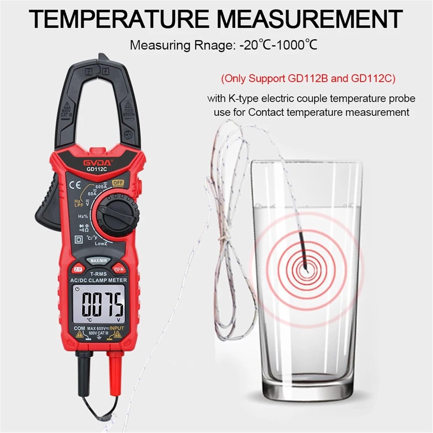
Image 5.1: The GD112B clamp meter displaying a temperature reading while a K-type thermocouple probe is immersed in a glass of water. This demonstrates the temperature measurement capability.
5.8 Continuity Test (Ω))))
- Ensure the circuit is de-energized.
- Connect the test leads as described in Section 4.2.
- Rotate the dial to the Ω))) position.
- Touch the test probes across the circuit or component. If continuity exists (resistance below a certain threshold), the meter will emit an audible beep.
5.9 Diode Test (→|)
- Ensure the circuit is de-energized.
- Connect the test leads as described in Section 4.2.
- Rotate the dial to the →| position.
- Touch the red probe to the anode and the black probe to the cathode of the diode. The display will show the forward voltage drop. Reverse the probes; the display should show 'OL' (Open Line) for a good diode.
5.10 Non-Contact Voltage (NCV) Detection
The NCV function allows for quick detection of AC voltage without direct contact.
- Rotate the dial to the NCV position.
- Move the top part of the clamp meter (the jaw area) close to the conductor or outlet you wish to test.
- If AC voltage is detected, the meter will emit an audible beep and the NCV indicator light will flash. The intensity of the beeping and flashing may increase with stronger voltage.

Image 5.2: The GD112B clamp meter's jaw is positioned near an electrical outlet, illustrating the Non-Contact Voltage (NCV) detection feature. Wavy lines indicate the detection field.
5.11 Using the LED Flashlight
The built-in LED flashlight can be activated to illuminate dark work areas.
- Press the flashlight button (often marked with a light bulb icon) to turn the flashlight ON.
- Press the button again to turn the flashlight OFF.
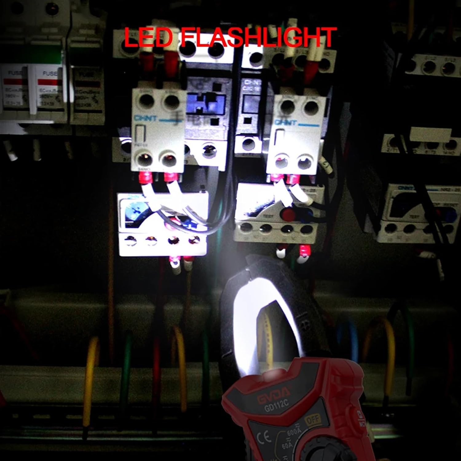
Image 5.3: The GD112B clamp meter's LED flashlight is shown illuminating a dark electrical panel, demonstrating its utility in low-light conditions.
5.12 Data Hold, MAX/MIN, LowZ, and LPF Functions
- Data Hold: Press the 'HOLD' button to freeze the current reading on the display. Press again to release.
- MAX/MIN: Press the 'MAX/MIN' button to enter MAX/MIN recording mode. The meter will display the maximum or minimum value detected. Press again to cycle through MAX, MIN, and current readings. Hold to exit.
- LowZ: Select the LowZ function on the rotary dial to measure voltage with a low input impedance, which helps to drain ghost voltages.
- LPF (Low Pass Filter): Select the LPF function on the rotary dial to filter out high-frequency noise when measuring AC voltage or current, useful for variable frequency drives.
6. Maintenance
6.1 Cleaning
To clean the meter, wipe the case with a damp cloth and a mild detergent. Do not use abrasives or solvents. Ensure the meter is completely dry before use.
6.2 Battery Replacement
Refer to Section 4.1 for detailed instructions on battery replacement. Always replace batteries when the low battery indicator appears on the display to maintain measurement accuracy.
6.3 Storage
If the meter is not to be used for an extended period, remove the batteries to prevent leakage and damage. Store the meter in a cool, dry place, away from direct sunlight and extreme temperatures.
7. Troubleshooting
If you encounter issues with your JDOUNFMO GD112B, refer to the following common problems and solutions:
- Meter does not power on: Check battery installation and ensure batteries are not depleted. Replace if necessary.
- No reading or 'OL' (Overload) displayed: Ensure test leads are properly connected. Verify the function and range selection are appropriate for the measurement. If measuring resistance, ensure the circuit is de-energized. 'OL' can also indicate a value beyond the meter's range.
- Inaccurate readings: Check battery level. Ensure test leads are making good contact. Verify the correct function and range are selected. Avoid strong electromagnetic interference.
- Continuity test does not beep: Ensure the circuit is de-energized. Check for open circuits or high resistance.
If problems persist, contact customer support.
8. Specifications (GD112B)
| Function | Range | Remarks |
|---|---|---|
| Display Counts | 6000 | |
| AC Voltage | 600mV / 6V / 60V / 600V | Auto Ranging |
| DC Voltage | 6V / 60V / 600V | Auto Ranging |
| AC Current | 6A / 60A / 600A | Clamp Measurement |
| DC Current | 6A / 60A / 600A | Clamp Measurement |
| Resistance | 600Ω / 6kΩ / 60kΩ / 600kΩ / 6MΩ / 60MΩ | Auto Ranging |
| Capacitance | 10nF / 100nF / 1uF / 10uF / 100uF / 1mF / 10mF / 100mF (99.9mF max) | Auto Ranging |
| Frequency | 10Hz / 100Hz / 1kHz / 10kHz / 100kHz / 1mHz / 10mHz | Auto Ranging |
| Duty Cycle | 1% - 99% | |
| Temperature | -20°C ~ 1000°C (-4°F ~ 1832°F) | Requires K-type thermocouple |
| Continuity | Yes | Audible beep |
| Diode Test | Yes | |
| NCV Detection | Yes | Non-Contact Voltage |
| True RMS | Yes | |
| LowZ | Yes | Low Impedance Voltage |
| LPF | Yes | Low Pass Filter |
| Data Hold | Yes | |
| MAX/MIN | Yes | |
| Auto Off | Yes | |
| Flashlight | Yes | |
| Power Supply | 2 x 1.5V AAA Batteries | Not included |
| Product Size | 193mm x 73mm | Approximate dimensions |
9. Warranty and Support
Specific warranty information for the JDOUNFMO GD112B Digital Clamp Meter is not provided in this manual. Please refer to the product packaging or contact your retailer for warranty details.
For technical support or inquiries, please contact JDOUNFMO customer service through the contact information provided with your purchase or on the official JDOUNFMO website.