1. Introduction
This manual provides detailed instructions for the installation, operation, and maintenance of the Generic MTR-12 Temperature Control Meter. Please read this manual thoroughly before using the device to ensure proper function and safety. The MTR-12 is designed for precise temperature regulation in water chillers and similar applications.
2. Safety Information
- Always disconnect power before installation, maintenance, or troubleshooting.
- Ensure all wiring connections comply with local electrical codes and standards.
- Do not operate the device in environments exceeding its specified temperature and humidity limits.
- Only qualified personnel should perform installation and service.
- Keep the device away from water and excessive moisture unless specifically designed for such environments.
3. Product Overview
The MTR-12 is a compact and reliable temperature control meter designed for accurate temperature management. It features a clear display and intuitive controls for setting desired temperatures and monitoring system status.
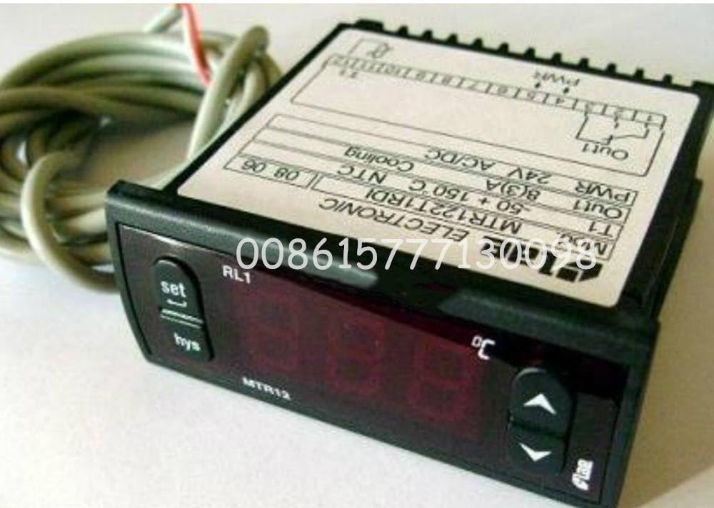
Figure 1: Front view of the Generic MTR-12 Temperature Control Meter. This image shows the digital display, control buttons, and the compact design of the unit.
Key Features:
- Digital temperature display
- Adjustable setpoint control
- Temperature sensor input
- Relay output for chiller control
4. Setup and Installation
4.1 Mounting
The MTR-12 is designed for panel mounting. Ensure adequate space for ventilation and access to wiring terminals. Cut a rectangular opening in the panel according to the dimensions provided in the specifications section.
4.2 Wiring
Refer to the wiring diagram below for correct connections. Ensure all power is disconnected before wiring.
- Connect the main power supply to the designated terminals (L and N).
- Connect the temperature sensor to the sensor input terminals. Observe polarity if applicable.
- Connect the chiller's control input to the relay output terminals (NO, NC, COM).
- Double-check all connections for security and correctness.
Note: A detailed wiring diagram is typically printed on the side of the unit or included in a separate diagram sheet. Always consult the physical product for precise terminal markings.
5. Operating Instructions
5.1 Power On
Once wired, apply power to the unit. The display will illuminate and show the current measured temperature.
5.2 Setting the Temperature Setpoint
- Press the SET button once. The display will flash, showing the current setpoint temperature.
- Use the UP and DOWN arrow buttons to adjust the setpoint to your desired temperature.
- Press the SET button again to confirm and save the new setpoint. The display will return to showing the current measured temperature.
5.3 Parameter Configuration (Advanced)
The MTR-12 may have advanced parameters for hysteresis, calibration, and alarm settings. To access these:
- Press and hold the SET button for 3-5 seconds until a parameter code appears.
- Use the UP and DOWN buttons to navigate through parameter codes.
- Press SET to view or edit a parameter's value.
- Use UP and DOWN to change the value, then SET to save.
- Exit the parameter menu by pressing and holding SET again or waiting for a timeout.
Consult the specific parameter list provided with your unit for detailed descriptions of each parameter code and its function.
6. Maintenance
6.1 Cleaning
Wipe the display and casing with a soft, damp cloth. Do not use abrasive cleaners or solvents, as these can damage the plastic and display. Ensure no liquid enters the device.
6.2 Sensor Inspection
Periodically inspect the temperature sensor and its wiring for any signs of damage, corrosion, or loose connections. A faulty sensor can lead to inaccurate temperature readings and improper control.
6.3 Electrical Connections
Check all electrical connections annually to ensure they remain tight and free from corrosion. Loose connections can cause intermittent operation or device failure.
7. Troubleshooting
| Problem | Possible Cause | Solution |
|---|---|---|
| Display is blank | No power supply; Loose wiring | Check power connections; Ensure power is supplied to the unit. |
| Inaccurate temperature reading | Faulty sensor; Sensor not properly installed; Calibration error | Check sensor wiring and placement; Replace sensor if damaged; Perform sensor calibration if available. |
| Chiller not turning on/off | Incorrect setpoint; Relay wiring error; Faulty relay | Verify setpoint and hysteresis settings; Check chiller control wiring; Test relay functionality. |
| Error code displayed | Specific system fault | Refer to the product's specific error code list for diagnosis and resolution. |
8. Specifications
| Parameter | Value |
|---|---|
| Model | MTR-12 (MTR122T1RD1) |
| Input Voltage | (Typically 110-240V AC, specific to model) |
| Temperature Range | (Specific to model, e.g., -50°C to 110°C) |
| Control Accuracy | (Specific to model, e.g., ±0.1°C) |
| Sensor Type | (Specific to model, e.g., NTC) |
| Output | Relay Output (e.g., 10A/250VAC) |
| Dimensions | (Specific to model, e.g., 75x34.5x85mm) |
| Mounting | Panel Mount |
Note: The exact specifications for input voltage, temperature range, control accuracy, sensor type, and dimensions should be verified from the product packaging or a dedicated specification sheet provided with your specific MTR-12 unit.
9. Warranty and Support
This Generic MTR-12 Temperature Control Meter is typically covered by a standard manufacturer's warranty against defects in materials and workmanship. The duration and terms of the warranty may vary. Please retain your proof of purchase for warranty claims.
For technical support, troubleshooting assistance beyond this manual, or warranty inquiries, please contact your retailer or the manufacturer's customer service department. Contact information is usually provided on the product packaging or the seller's website.