Introduction
The JDOUNFMO GD168B is a high-performance intelligent digital clamp meter designed for a wide range of electrical measurements. It combines multiple functions to enhance efficiency and safety in electrical testing. This manual provides detailed instructions for the proper use and maintenance of your device.
Key features include:
- HD Colour LCD Display
- Maximum 6000 Counts display
- Non-contact AC voltage measurement (NCV)
- AC Inrush current measurement
- MAX/MIN value measurement
- Live wire detection
- Auto power off
- Low battery indication
- Over range indication
- DCA zero function

Figure 1: JDOUNFMO GD168B Digital Clamp Meter. This image shows the front view of the red and black clamp meter with its display and function buttons, along with the red and black test leads connected.
Package Contents
Verify that all items are present in the package:
- JDOUNFMO GD168B Digital Clamp Meter
- Test Leads (Red and Black)
- Temperature Probe
- User Manual
- Carrying Bag
- Gift Box
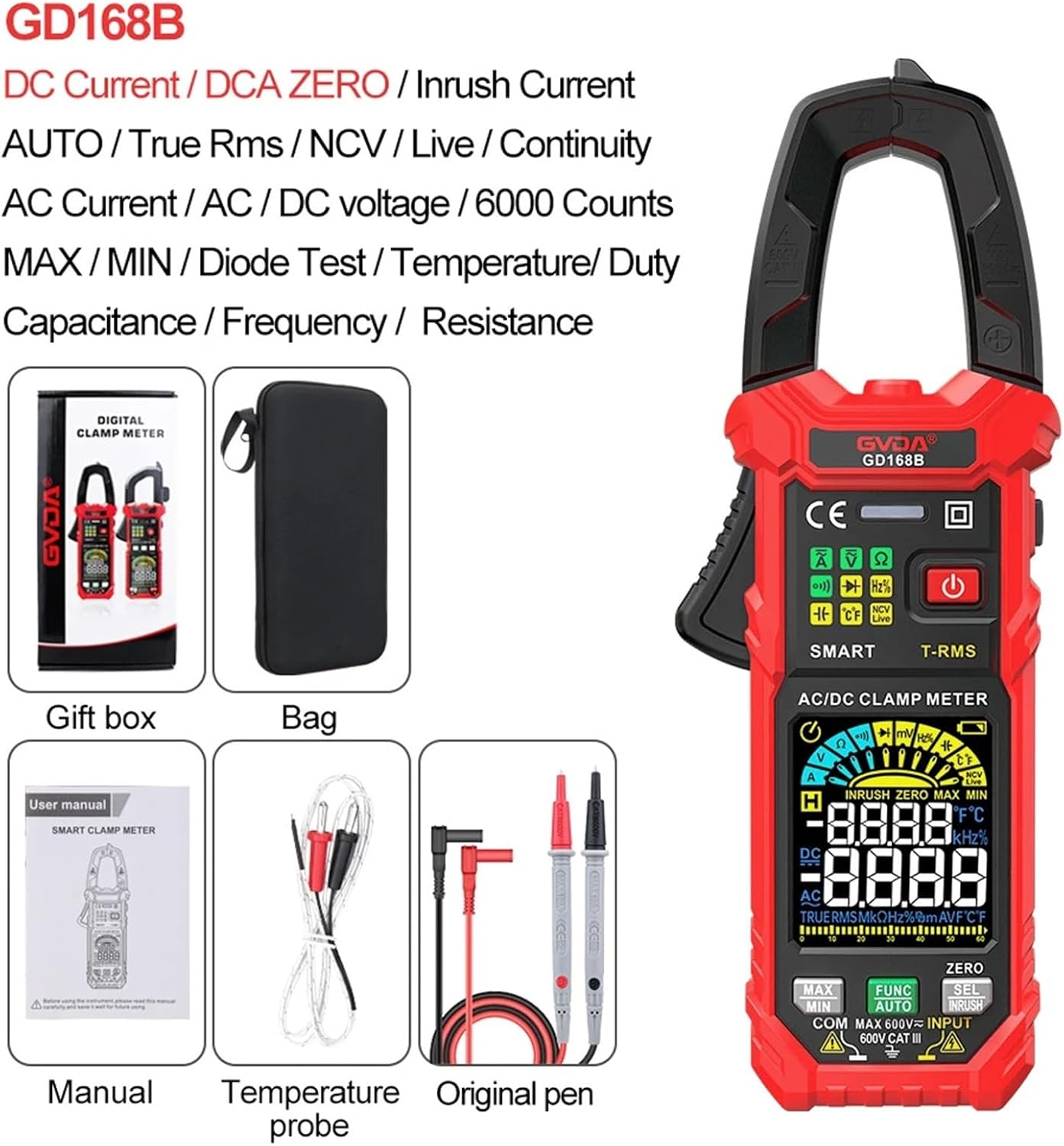
Figure 2: Package Contents. This image displays the clamp meter, a carrying bag, the user manual, a temperature probe, and original test leads, all neatly arranged.
Setup
1. Battery Installation
The GD168B typically uses standard batteries (e.g., AAA). Locate the battery compartment on the back of the device. Open the compartment cover, insert the batteries according to the polarity markings, and securely close the cover.
2. Connecting Test Leads
Insert the red test lead into the "INPUT" jack and the black test lead into the "COM" (Common) jack. Ensure they are fully seated for a secure connection.
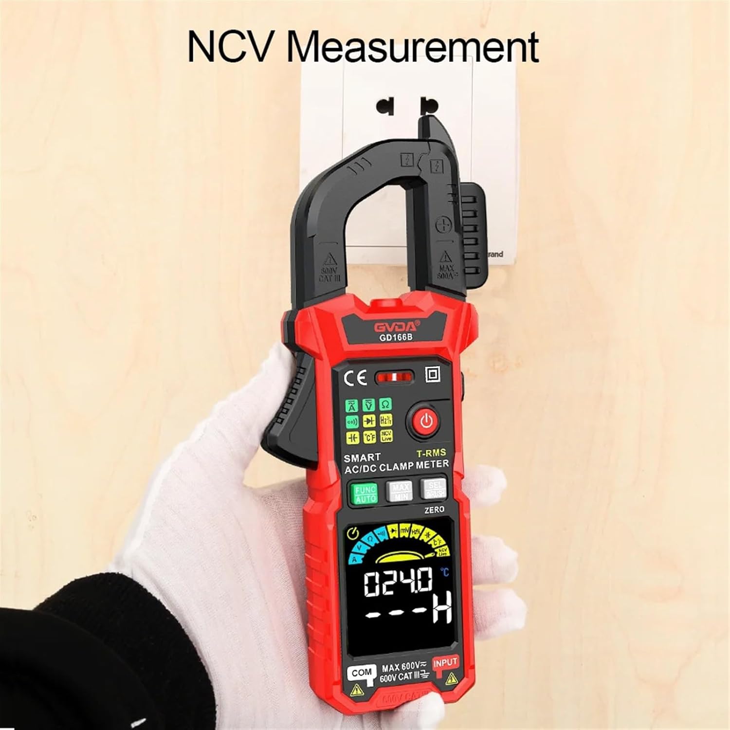
Figure 3: Proper Test Lead Placement. This image illustrates how to correctly insert the test leads into the designated ports on the clamp meter, showing the red lead in the input and black in common.
3. Powering On/Off
Press and hold the power button (⏻) to turn the device on or off. The HD Colour LCD display will illuminate upon activation.
Operating Instructions
1. Function Selection
The GD168B features an "AUTO" mode for automatic range selection. For specific measurements, use the FUNC button to cycle through available functions (e.g., Voltage, Resistance, Capacitance, Frequency, Diode, Continuity, Temperature).
2. AC/DC Voltage Measurement
Connect the test leads in parallel to the circuit or component. Select the appropriate voltage range (or use AUTO mode). The display will show the voltage reading.
3. AC/DC Current Measurement (Clamp Function)
To measure current, open the clamp jaws and enclose a single conductor. Ensure the conductor is centered within the jaws. The display will show the current reading. For DC current, use the ZERO button to zero the reading before measurement if necessary.
4. Inrush Current Measurement
This function measures the initial surge of current when a device is powered on. Select the Inrush Current mode (often labeled INRUSH or accessible via SEL button). Clamp around the conductor of the device to be tested and power on the device. The meter will capture the peak inrush current.

Figure 4: Inrush Current Measurement. This image shows the clamp meter measuring inrush current on electrical wiring within a control panel, with the display showing a current reading.
5. Non-Contact Voltage (NCV) Measurement
Activate the NCV function. Bring the top of the clamp meter near a live AC voltage source without direct contact. The meter will indicate the presence of AC voltage through audible beeps and/or visual indicators on the display.

Figure 5: NCV Measurement. This image depicts the clamp meter being used to detect non-contact voltage near an electrical outlet, with the display showing an NCV reading.
6. Resistance, Capacitance, Frequency, Duty Cycle, Diode, and Continuity
Use the FUNC button to select the desired measurement mode. Connect the test leads to the component or circuit as appropriate for each measurement type. Refer to the display for readings.
7. Temperature Measurement
Connect the temperature probe to the meter. Select the temperature measurement mode. Place the probe tip on or near the object whose temperature is to be measured. The display will show the temperature in Celsius or Fahrenheit.
8. MAX/MIN Value Measurement
Press the MAX/MIN button during a measurement to record the maximum and minimum values detected. Press again to cycle between MAX, MIN, and current readings.
9. Data Hold
Press the HOLD button (often integrated with another function or a dedicated button) to freeze the current reading on the display. Press again to release.
10. Backlight and Flashlight
The meter features a backlight for improved visibility in low-light conditions and a flashlight for illuminating the work area. Refer to the device buttons for activation (often a short press of the power button or a dedicated light button).
Maintenance
1. Cleaning
Wipe the meter's casing with a damp cloth. Do not use abrasive cleaners or solvents. Ensure the device is powered off and disconnected from any circuits before cleaning.
2. Battery Replacement
When the low battery indicator appears on the display, replace the batteries promptly to ensure accurate readings. Follow the battery installation steps outlined in the Setup section.
3. Storage
Store the clamp meter in its carrying bag in a cool, dry place, away from direct sunlight and extreme temperatures. Remove batteries if storing for extended periods to prevent leakage.
Troubleshooting
1. Display shows "OL" (Over Range)
This indicates that the measured value exceeds the selected range. If in manual range mode, select a higher range. If in AUTO mode, the value is beyond the meter's maximum capability for that function.
2. No display or faint display
Check battery levels. Replace batteries if the low battery indicator is on or if the display is dim. Ensure the meter is powered on correctly.
3. Inaccurate readings
Ensure test leads are properly connected and not damaged. Verify the correct function and range are selected. For current measurements, ensure only a single conductor is within the clamp jaws.
4. Meter does not respond
Try turning the meter off and on again. If the issue persists, replace the batteries.
Specifications
| Parameter | Value |
|---|---|
| Display | 6000 Counts, HD Colour LCD |
| DC Voltage | 600mV, 6V, 60V, 600V |
| AC Voltage | 600mV, 6V, 60V, 600V (True RMS) |
| AC Current | 60A, 600A |
| DC Current | 60A, 600A |
| Resistance | 600Ω, 6KΩ, 60KΩ, 600KΩ, 6MΩ, 60MΩ |
| AC Inrush Current | 60A, 600A |
| Capacitance | 6nF, 60nF, 600uF, 6uF, 60uF, 600uF; 6mF, 60mF |
| Frequency | 100Hz, 1000Hz, 10KHz, 100KHz, 1000KHz, 10MHz |
| Duty Cycle | 1-99% |
| Temperature | -40℃~1000℃, -40℉~1832℉ |
| Max. Voltage (Terminals to Earth) | 600V |
| Over Range Indication | "OL" |
| Low Battery Indication | Yes |
| Input Polarity Indication | Display "-" |
| Continuity Test | Yes |
| Diode Measurement | Yes |
| Smart (AUTO) Measurement | Yes |
| Live Wire Detection | Yes |
| Clamp Opening Size | 36mm |
| Item Weight | 1.76 ounces |
| Package Dimensions | 1.18 x 0.79 x 0.39 inches |
Warranty and Support
For warranty information or technical support, please refer to the documentation included with your purchase or contact JDOUNFMO customer service through their official channels. Keep your purchase receipt for warranty claims.