1. Introduction
This manual provides detailed instructions for the installation, operation, and maintenance of your Thermaltake S200 Plus TG ARGB Mid Tower Computer Chassis. Please read this manual thoroughly before beginning assembly to ensure correct setup and optimal performance. Retain this manual for future reference.

Figure 1.1: Thermaltake S200 Plus TG ARGB Mid Tower Chassis Overview
2. Safety Information
Observe the following safety precautions during installation and operation:
- Always disconnect the power supply from the wall outlet before installing or removing any components.
- Wear an anti-static wrist strap to prevent electrostatic discharge (ESD) damage to components.
- Handle components carefully to avoid physical damage.
- Keep the chassis away from water, moisture, and extreme temperatures.
- Ensure proper ventilation to prevent overheating.
3. Package Contents
Verify that all items are present in your package:
- Thermaltake S200 Plus TG ARGB Mid Tower Chassis
- 4 x 120mm ARGB Lite Fans (3 pre-installed front, 1 pre-installed rear)
- Accessory Box (screws, zip ties, standoffs, etc.)
- User Manual (this document)
4. Component Overview
Familiarize yourself with the key features and components of your chassis.
4.1. Exterior Views

Figure 4.1: Angled view of the chassis
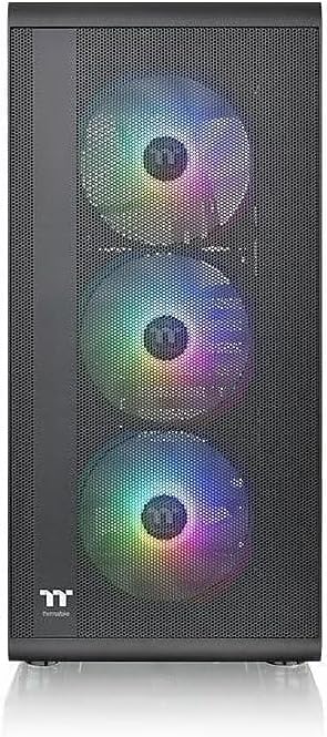
Figure 4.2: Front view of the chassis

Figure 4.3: Mesh Front Panel for optimized airflow
4.2. Interior Views

Figure 4.4: Interior layout with tempered glass side panel removed

Figure 4.5: Tempered Glass Side Panel

Figure 4.6: Built-in PSU Cover for cable management
4.3. Front I/O Ports

Figure 4.7: Front I/O Panel
- Power Button: Turns the system on/off.
- Reset Button: Restarts the system.
- USB 3.0 Ports (x2): For high-speed data transfer.
- HD Audio Jacks (Headphone/Microphone): For audio input/output.
5. Setup and Installation
Follow these steps to install your PC components into the chassis.
5.1. Preparing the Chassis
- Place the chassis on a flat, stable surface.
- Remove the tempered glass side panel by unscrewing the thumb screws and carefully pulling it away.
- Remove the right-side panel by unscrewing the thumb screws and sliding it backward.
5.2. Motherboard Installation
- Install the necessary standoffs for your motherboard form factor (Mini ITX, Micro ATX, or ATX).
- Align your motherboard with the standoffs and the I/O shield opening.
- Secure the motherboard with the provided screws.
5.3. Power Supply Unit (PSU) Installation
- Position the PSU into the dedicated compartment at the bottom rear of the chassis.
- Ensure the PSU fan faces downwards (if the chassis has a bottom vent) or upwards.
- Secure the PSU with screws from the rear of the chassis.
5.4. Storage Drive Installation
The chassis supports 2 x 3.5" drives and 2 x 2.5" drives.
- 3.5" HDD: Install into the drive cage located under the PSU shroud.
- 2.5" SSD/HDD: Mount onto the dedicated trays behind the motherboard tray.
5.5. Graphics Card (VGA) Installation
- Remove the necessary expansion slot covers from the rear of the chassis.
- Insert your graphics card into the appropriate PCIe slot on the motherboard.
- Secure the graphics card with screws.
5.6. Fan and Radiator Support
The chassis comes with four pre-installed 120mm ARGB Lite fans. Additional cooling options are available:

Figure 5.1: Fan Support List
- Front: 3 x 120mm or 2 x 140mm fans (3 x 120mm ARGB fans pre-installed).
- Top: 2 x 120mm or 2 x 140mm fans.
- Rear: 1 x 120mm fan (1 x 120mm ARGB fan pre-installed).

Figure 5.2: All-in-One (AIO) Radiator Compatibility List
- Front: 1 x 360mm or 1 x 280mm radiator.
- Top: 1 x 240mm radiator.
- Rear: 1 x 120mm radiator.
5.7. Cable Management
Utilize the space behind the motherboard tray and the PSU shroud to route and hide cables for a clean build and improved airflow. Use the provided zip ties to secure cables.
6. Operating Instructions
6.1. Powering On/Off
Press the power button on the front I/O panel to turn your system on or off. A short press typically initiates a soft shutdown, while a long press (4-5 seconds) forces a hard shutdown.
6.2. ARGB Fan Control
The pre-installed ARGB fans are compatible with motherboard RGB software from major brands such as ASUS Aura Sync, GIGABYTE RGB Fusion, MSI Mystic Light Sync, and ASRock Polychrome Sync. Connect the ARGB cables to your motherboard's 5V addressable RGB header and use the motherboard's software to customize lighting effects.
7. Maintenance
7.1. Cleaning
- Dust Filters: Regularly remove and clean the dust filters (front, top, bottom) to maintain optimal airflow and prevent dust buildup inside the chassis. Use compressed air or rinse with water and allow to dry completely before reinstallation.
- Exterior: Wipe the exterior surfaces with a soft, damp cloth. Avoid abrasive cleaners or solvents.
- Interior: Use compressed air to remove dust from internal components periodically. Ensure the system is powered off and unplugged before cleaning.
8. Troubleshooting
If you encounter issues, refer to these common troubleshooting steps:
- System Not Powering On:
- Check all power connections (PSU to wall, PSU to motherboard, CPU, GPU).
- Ensure the power button cable is correctly connected to the motherboard's front panel header.
- Verify the PSU switch is in the 'ON' position.
- Fans Not Spinning / RGB Not Working:
- Check fan power cables and ARGB cables are securely connected to the motherboard or fan controller.
- Ensure ARGB cables are connected to a 5V addressable RGB header, not a 12V RGB header.
- Verify motherboard RGB software is installed and configured correctly.
- Poor Airflow / Overheating:
- Clean all dust filters and internal components.
- Ensure fans are oriented correctly for intake and exhaust.
- Check for any obstructions to airflow inside the chassis.
9. Specifications
Detailed technical specifications for the Thermaltake S200 Plus TG ARGB Mid Tower Chassis (Model: CA-1X2-00M1WN-01).

Figure 9.1: Component Clearance Information
| Feature | Specification |
|---|---|
| Model | S200 Plus TG ARGB (CA-1X2-00M1WN-01) |
| Case Type | Mid Tower |
| Dimensions (H x W x D) | 460 x 210 x 395.3 mm (18.11 x 8.27 x 15.56 inch) |
| Weight | 4.9 kg / 10.8 lbs |
| Side Panel | 1 x Tempered Glass |
| Color | Black |
| Material | SPCC Steel, Tempered Glass |
| Motherboard Compatibility | Mini ITX, Micro ATX, ATX |
| Drive Bays | 2 x 3.5" or 2 x 2.5" (HDD Cage); 2 x 2.5" (Behind M/B Tray) |
| Expansion Slots | 7 |
| I/O Ports | 2 x USB 3.0, 1 x HD Audio, 1 x Reset Button |
| PSU Support | Standard PS2 PSU (Bottom Mount) |
| CPU Cooler Max Height | 166 mm |
| VGA Max Length | 330 mm (without radiator), 300 mm (with radiator) |
| PSU Max Length | 190 mm (with HDD Cage) |
| Pre-installed Fans | Front: 3 x 120mm ARGB Lite Fan; Rear: 1 x 120mm ARGB Lite Fan |
10. Warranty Information
This Thermaltake chassis comes with a 3-Year Warranty from the date of purchase. The warranty covers defects in materials and workmanship under normal use. For detailed warranty terms and conditions, please refer to the official Thermaltake website or contact customer support.
11. Support
For further assistance, technical support, or to download the latest drivers and software, please visit the official Thermaltake website:
You may also contact Thermaltake customer service for direct support.