
1. Safety Information
Please read and understand all safety information before operating this device. Failure to follow these instructions may result in electric shock, fire, or personal injury.
- This device is designed for professional use and should only be operated by qualified personnel.
- Do not use the meter if it appears damaged or if the test leads are compromised.
- Observe all local and national safety codes.
- Always ensure the meter is set to the correct function and range before making measurements.
- Avoid contact with live circuits. Use appropriate personal protective equipment (PPE).
- The device is rated CAT III 600V. Do not exceed these voltage limits.
2. Product Overview
The ZOYI ZT-QB1 is a smart clamp meter designed for accurate electrical measurements. It features a simple panel for ease of use, a flashlight, and backlight for visibility in various conditions.
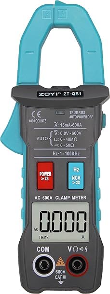
Figure 2.1: Front view of the ZOYI ZT-QB1 Smart Clamp Meter, displaying its digital screen, function buttons, and clamp jaws.
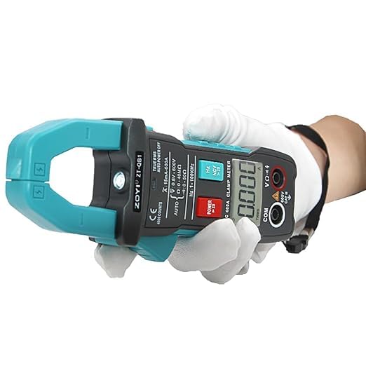
Figure 2.2: The ZOYI ZT-QB1 Smart Clamp Meter being held, illustrating its ergonomic design and the position of the clamp jaws and measurement ports.
Key Features:
- AC/DC Voltage Measurement
- AC Current Measurement (up to 600A)
- Resistance Measurement
- Frequency Measurement
- Continuity Test
- Non-Contact Voltage (NCV) Detection
- Inrush Current Measurement
- Peak Hold Voltage
- Smart Mode for automatic measurement identification
- True-RMS for accurate AC measurements
- Data Hold function
- Flashlight and Backlight for low-light conditions
- Low Battery Alert and Auto Power Off
3. Setup
3.1 Battery Installation
The ZT-QB1 requires batteries for operation. The device typically comes with batteries included.
- Locate the battery compartment cover on the back of the meter.
- Use a screwdriver to open the battery compartment.
- Insert the batteries, observing the correct polarity (+ and -).
- Replace the battery compartment cover and secure it with the screw.
3.2 Connecting Test Leads
For voltage, resistance, frequency, and continuity measurements, connect the included test leads.
- Insert the black test lead into the 'COM' (common) input jack.
- Insert the red test lead into the 'VΩK' input jack.
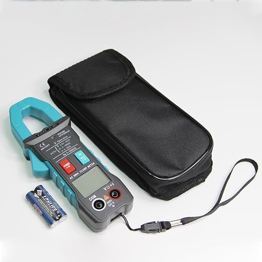
Figure 3.1: The ZOYI ZT-QB1 Smart Clamp Meter shown with its included test leads and carrying pouch, alongside two AAA batteries.
4. Operating Instructions
4.1 Power On/Off
Press the POWER button to turn the meter on. The meter will automatically enter Smart Mode. Press and hold the POWER button to turn it off.
4.2 Smart Mode (AUTO)
In Smart Mode, the meter automatically identifies and measures AC/DC voltage, resistance, and continuity without manual range selection. This is the default mode upon power-on.
4.3 AC Current Measurement (Clamp Function)
To measure AC current, use the clamp jaws:
- Ensure the meter is in AC Current mode (indicated on the display).
- Open the clamp jaws by pressing the trigger.
- Encircle only one conductor of the circuit with the clamp jaws. Do not clamp around multiple conductors, as this will result in an inaccurate reading.
- Close the clamp jaws securely. The AC current reading will be displayed.
4.4 Voltage Measurement (AC/DC)
With test leads connected:
- In Smart Mode, the meter will automatically detect AC or DC voltage.
- Connect the red test lead to the positive side of the circuit and the black test lead to the negative/common side.
- The voltage reading will be displayed.
4.5 Resistance Measurement
With test leads connected:
- Ensure the circuit is de-energized before measuring resistance.
- In Smart Mode, the meter will automatically detect resistance.
- Connect the test leads across the component to be measured.
- The resistance value will be displayed in Ohms (Ω).
4.6 Continuity Test
With test leads connected:
- Ensure the circuit is de-energized.
- In Smart Mode, the meter will automatically detect continuity.
- Connect the test leads across the circuit or component.
- A continuous beep indicates a complete circuit (continuity).
4.7 NCV (Non-Contact Voltage) Detection
Press the NCV button to activate NCV mode. Hold the top of the meter near a live conductor. The meter will beep and the NCV indicator will light up when AC voltage is detected.
4.8 Inrush Current Measurement
This function measures the initial surge of current when a device is turned on. Refer to the specific instructions in the full manual for precise usage.
4.9 Peak Hold Voltage
This feature captures and displays the maximum voltage peak detected during a measurement. Consult the detailed manual for activation and interpretation.
4.10 Special Functions
- Data Hold: Press the 'HOLD' button (usually on the side) to freeze the current reading on the display. Press again to release.
- Flashlight/Backlight: The meter includes a flashlight for illuminating the measurement area and a backlight for the display in low-light conditions. These are typically activated by dedicated buttons or a long press of a function button.
- Auto Power Off: To conserve battery life, the meter will automatically power off after a period of inactivity.
5. Maintenance
5.1 Cleaning
Wipe the meter with a dry, soft cloth. Do not use abrasives or solvents. Ensure the meter is powered off and disconnected from any circuits before cleaning.
5.2 Battery Replacement
When the low battery indicator appears on the display, replace the batteries promptly to ensure accurate readings. Follow the battery installation steps in Section 3.1.
5.3 Storage
Store the meter in a cool, dry place, away from direct sunlight and extreme temperatures. If storing for an extended period, remove the batteries to prevent leakage.
6. Troubleshooting
- Meter does not power on: Check battery installation and ensure batteries are not depleted.
- Inaccurate readings: Verify test lead connections, ensure the correct measurement mode is selected (if not using Smart Mode), and check for external interference.
- No continuity beep: Ensure the circuit is de-energized and the test leads are making good contact.
- Display is dim: Replace batteries or activate the backlight function.
7. Specifications
| Specification | Value |
|---|---|
| Brand | Skyking, ZOYI |
| Model | ZT-QB1 |
| Display Counts | 4000 |
| AC Voltage Range | 0-600V |
| DC Voltage Range | 0-600V |
| AC Current Range | 0-600A |
| Resistance Range | 0-60MΩ |
| Frequency Range | 1Hz-100kHz |
| Safety Rating | CAT III 600V |
| Power Source | Battery Powered |
| Item Weight | 220 Grams |
| Product Dimensions (L x W x H) | 8 x 3 x 4 Centimeters |
| Included Components | ZOYI ZT-QB1, Test Leads |
| Country of Origin | China |
8. Warranty and Support
This product is covered by a standard manufacturer's warranty against defects in materials and workmanship. For specific warranty terms and conditions, please refer to the documentation provided with your purchase or contact the retailer.
Customer Support:
For technical assistance, troubleshooting, or warranty claims, please contact your point of purchase or the manufacturer's customer service department. Contact details can typically be found on the product packaging or the manufacturer's official website.