1. Introduction
This manual provides essential information for the proper installation, operation, and maintenance of the FMSISIGQJ SHF-17-III Precision Harmonic Reducer with a 100:1 reduction ratio. This integrated harmonic reducer is designed for applications requiring high precision, low backlash, and compact size, such as industrial robotics and automation systems. Please read this manual thoroughly before using the product to ensure safe and efficient operation.
2. Safety Information
Observe the following safety precautions to prevent injury to personnel and damage to the equipment:
- Always disconnect power to the system before performing any installation, maintenance, or inspection.
- Ensure the reducer is securely mounted to a stable surface to prevent movement during operation.
- Do not exceed the specified torque and speed ratings to avoid damage to the reducer and connected machinery.
- Wear appropriate personal protective equipment (PPE) when handling or working near the reducer.
- Keep hands and loose clothing away from moving parts during operation.
- Consult a qualified technician for any repairs or modifications.
3. Product Overview
The SHF-17-III is an integrated harmonic drive reducer known for its compact design and high performance. It utilizes strain wave gearing technology to achieve a high reduction ratio with minimal backlash, making it suitable for precise motion control applications.
3.1 Key Features
- High Reduction Ratio: Achieves a 100:1 reduction ratio in a single stage.
- Low Backlash: Designed for near zero-backlash performance, ensuring high positional accuracy.
- Compact and Lightweight: Optimized for applications with stringent space and weight requirements.
- High Torque Capacity: Capable of handling significant torque loads relative to its size.
- Easy Integration: Designed for straightforward assembly into various systems.
3.2 Components and Dimensions
The SHF-17-III reducer consists of a circular spline, flexspline, and wave generator, integrated into a robust housing. The following images illustrate the product's external appearance and internal structure.

Figure 1: Top view of the FMSISIGQJ SHF-17-III Harmonic Reducer, showing the mounting holes and central shaft interface.

Figure 2: Internal view of the FMSISIGQJ SHF-17-III Harmonic Reducer, illustrating the strain wave gearing mechanism and ball bearings.
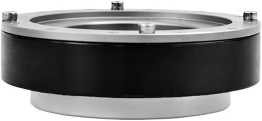
Figure 3: Side view of the FMSISIGQJ SHF-17-III Harmonic Reducer, highlighting its compact profile.
4. Setup and Installation
The FMSISIGQJ SHF-17-III reducer is supplied as an integrated unit and does not require internal assembly. Installation primarily involves mounting the unit and connecting it to the motor and driven load.
4.1 Mounting
- Ensure the mounting surface is clean, flat, and rigid enough to support the reducer and any applied loads.
- Align the reducer with the motor shaft and the driven load. Minimize any misalignment to prevent premature wear and reduce operational noise.
- Secure the reducer using appropriate fasteners through the designated mounting holes. Tighten fasteners to the manufacturer's recommended torque specifications (refer to system design documentation).
4.2 Shaft Connection
Connect the input shaft of the reducer to the motor and the output shaft to the driven mechanism. Use appropriate couplings that can accommodate any minor misalignment and transmit torque effectively without introducing excessive stress on the shafts or bearings.
5. Operating Instructions
Once installed, the harmonic reducer is ready for operation. Adhere to the specified operating parameters to ensure optimal performance and longevity.
- Input Speed: Do not exceed the maximum allowable input speed of 7000 r/min. The average input speed should ideally remain below 3500 r/min for continuous operation.
- Torque Loading: Operate within the rated torque specifications. Exceeding the allowable peak or instantaneous maximum torque can lead to damage.
- Temperature: Ensure the operating environment temperature is within the recommended range for industrial machinery. Excessive heat can degrade performance and lifespan.
- Vibration and Noise: Monitor the reducer for unusual vibration or noise, which may indicate misalignment, improper mounting, or internal issues.
6. Maintenance
Regular maintenance is crucial for maintaining the performance and extending the lifespan of your harmonic reducer.
- Inspection: Periodically inspect the reducer for any signs of wear, damage, or loose fasteners. Check for lubricant leakage.
- Lubrication: Harmonic reducers are typically pre-lubricated for life. However, consult the system's overall maintenance schedule for any specific lubrication requirements related to the application environment.
- Cleaning: Keep the exterior of the reducer clean and free from dust, debris, and corrosive substances.
- Environmental Conditions: Ensure the operating environment remains within specified parameters regarding temperature and humidity.
7. Troubleshooting
This section provides guidance for common issues that may arise during the operation of the harmonic reducer.
| Problem | Possible Cause | Solution |
|---|---|---|
| Excessive Noise/Vibration | Misalignment of shafts; Loose mounting bolts; Damaged bearings; Overload. | Check and correct alignment; Tighten mounting bolts; Inspect and replace bearings if necessary; Reduce load to within specifications. |
| Reduced Output Torque | Overload condition; Internal wear or damage; Incorrect input speed. | Verify load is within rated torque; Inspect internal components (professional service recommended); Ensure input speed is stable and correct. |
| Overheating | Excessive load; High ambient temperature; Insufficient cooling. | Reduce load; Improve ventilation around the reducer; Check for obstructions to airflow. |
| Backlash Increase | Normal wear over extended use; Internal component damage. | This is typically a sign of end-of-life or severe damage. Replacement or professional repair may be required. |
If issues persist after attempting these solutions, contact FMSISIGQJ customer support or a qualified service technician.
8. Specifications
Detailed technical specifications for the FMSISIGQJ SHF-17-III Harmonic Reducer (Reduction Ratio 100).
| Parameter | Value |
|---|---|
| Model | SHF-17-III |
| Type | Harmonic Reducer (Integrated Type) |
| Reduction Ratio | 100:1 |
| Diameter | 80 mm |
| Thickness | 26.5 mm |
| Weight | 0.53 kg (approx. 1.17 lbs) |
| Rated Torque (Input 2000 r/min) | 23 N.m |
| Allowable Peak Torque (Start/Stop) | 52 N.m |
| Allowable Max Average Load Torque | 38 N.m |
| Instantaneous Maximum Allowable Torque | 108 N.m |
| Allowable Maximum Input Speed | 7000 r/min |
| Allowable Average Input Speed | 3500 r/min |
| Positional Accuracy (Arc sec) | 10 |
| Assembly Required | No |
| Number of Pieces | 1 |

Figure 4: Technical drawing illustrating the dimensions and mounting points of the SHF-17-III Harmonic Reducer.
9. Warranty and Support
For information regarding product warranty, technical support, or service, please contact FMSISIGQJ customer service. Ensure you have your product model number (SHF-17-III) and purchase details available when contacting support.
Contact information can typically be found on the manufacturer's official website or through your point of purchase.