1. Introduction
This manual provides detailed instructions for the installation, operation, and maintenance of your Vikye KYZ-20A Intelligent PWM Solar Charge Controller. This device is designed to manage the power flow from your solar panels to your battery bank, ensuring efficient charging and protecting your batteries from overcharge and over-discharge. It features a 3-stage PWM charge management system, an industrial microcontroller, and a clear LCD display with a backlight for easy monitoring and adjustment of parameters.
2. Important Safety Instructions
- Ensure your battery has sufficient voltage for the controller to recognize the battery type before the first installation.
- The battery cable should be as short as possible to minimize power loss.
- The charge controller is designed for regulating solar modules only. Do not connect any other charging source to the controller.
- The controller will generate heat during operation. Ensure adequate ventilation around the unit.
- Always connect the battery first, then the solar panel, and finally the load. Disconnect in the reverse order.
- Avoid short circuits on the battery, solar panel, and load terminals.
- This device is for indoor use only. Protect it from water, moisture, and direct sunlight.
- Consult a qualified electrician if you are unsure about any part of the installation.
3. Product Overview
The Vikye KYZ-20A Solar Charge Controller features a robust design with an intuitive LCD display and multiple protection functions. It supports both 12V and 24V battery systems and offers a 2A USB output for charging small devices.
3.1 Key Features
- Industrial microcontroller for adjustable charge and discharge parameters.
- Full 3-stage PWM charge management.
- Comprehensive protection functions: over-current, short circuit, open circuit, reverse connection.
- Large LCD display with backlight for clear visibility, especially at night.
- Switchable charging function for lithium and lead-acid batteries.
- Integrated 5V/2A USB output.
3.2 Component Identification

Figure 1: Front view of the KYZ-20A Solar Charge Controller. This image displays the front of the controller, highlighting the LCD screen, control buttons, and the six terminal connections at the bottom.

Figure 2: Side view of the KYZ-20A Solar Charge Controller terminals. This image shows the six screw terminals for connecting the battery, solar panel, and DC load, along with the DC output port.
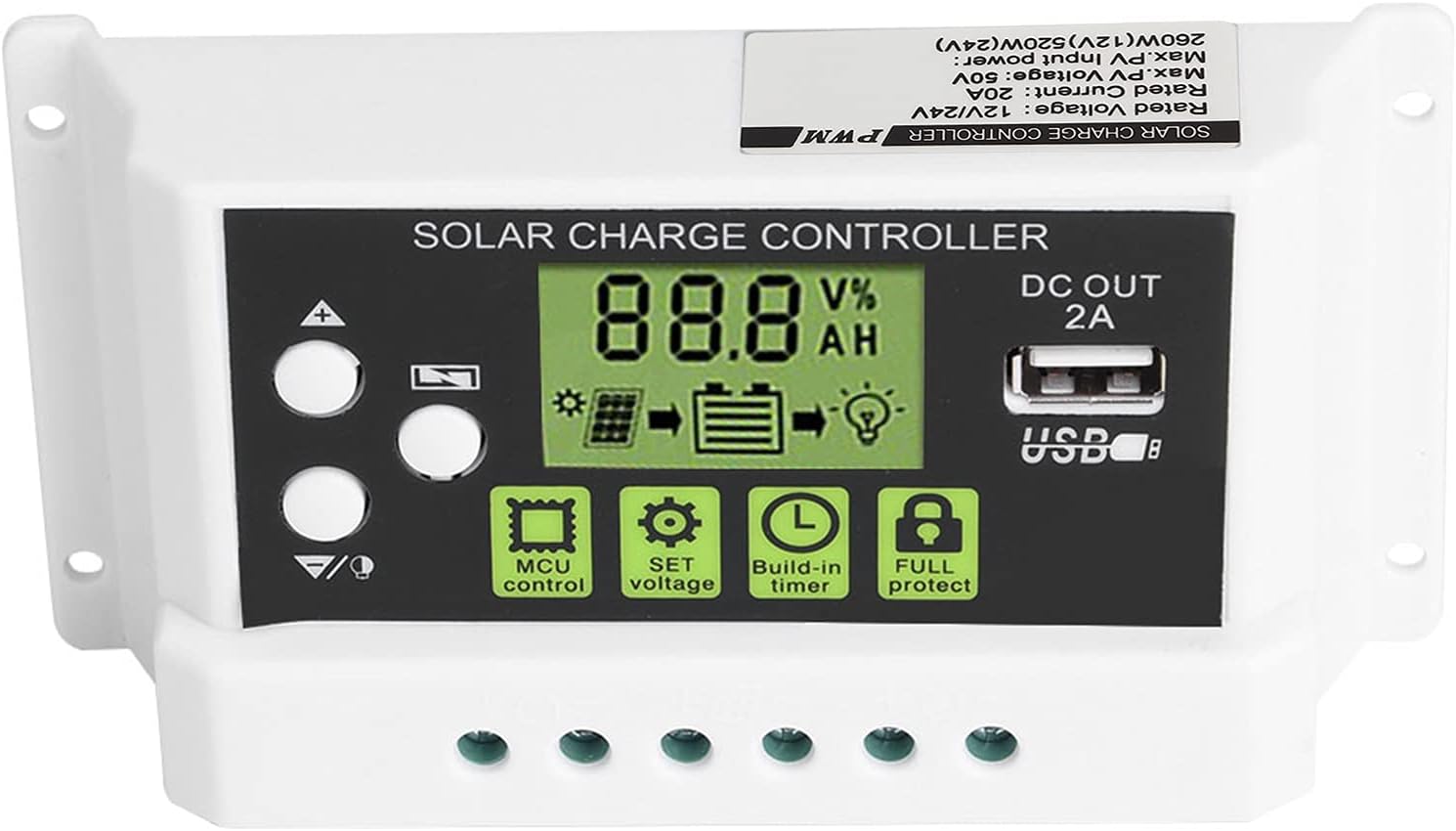
Figure 3: Close-up of the LCD display and control buttons. This image provides a detailed view of the LCD screen, showing battery voltage, charge/discharge status, and icons for MCU control, SET voltage, Build-in timer, and Full protect functions. The USB output port is also visible.

Figure 4: LCD display with backlight function. This image illustrates the controller's screen with its backlight active, enhancing visibility in low-light conditions.
4. Installation
Follow these steps carefully to install your solar charge controller. Incorrect installation can damage the device or other components.
- Prepare the Installation Site: Choose a dry, well-ventilated indoor location away from direct sunlight, high temperatures, and moisture. Ensure there is enough space around the controller for heat dissipation.
- Connect the Battery: Connect the battery to the charge controller first. Ensure the battery has sufficient voltage (at least 10V for 12V systems, 20V for 24V systems) for the controller to recognize the battery type. Connect the positive (+) and negative (-) terminals correctly. The battery cable should be as short as possible to minimize voltage drop.
- Connect the Solar Panel: Connect the solar panel to the charge controller. Ensure correct polarity (+ to + and - to -). The controller is designed for solar modules only; do not connect other power sources.
- Connect the DC Load (Optional): If you have a DC load, connect it to the load terminals of the controller. Ensure correct polarity.
- Verify Connections: Double-check all connections for correct polarity and secure fastening.
Important Note: Disconnect components in the reverse order: first the load, then the solar panel, and finally the battery.
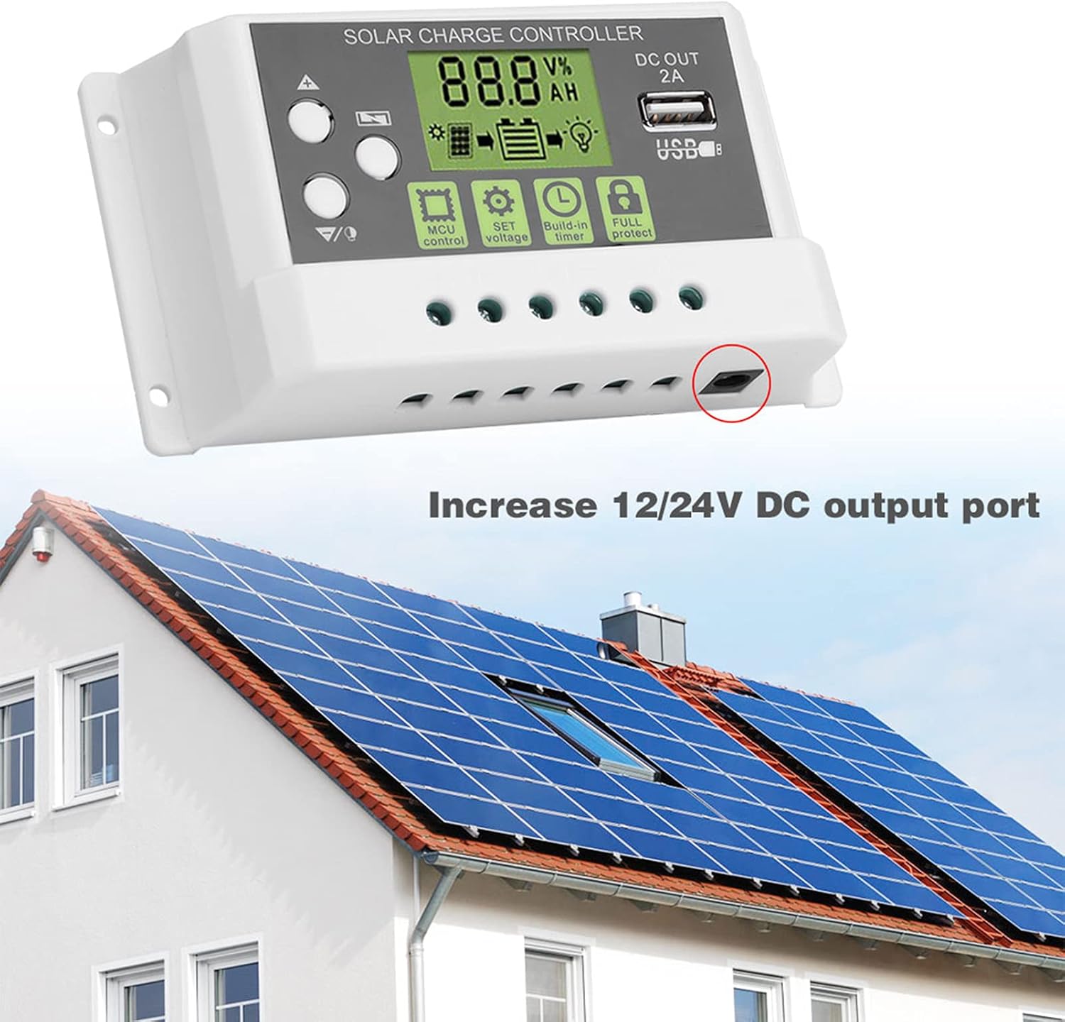
Figure 5: Example installation diagram. This image illustrates the general setup of the solar charge controller within a solar power system, connecting to solar panels and a battery bank, and highlighting the DC output port.
5. Operation
The controller's LCD display provides real-time system information, and the buttons allow for parameter adjustments.
5.1 LCD Display and Buttons
The LCD screen displays various parameters such as battery voltage, charging current, discharging current, and battery state of charge. The backlight function improves visibility in dark environments.
- Up/Down Buttons: Used to navigate through display menus and adjust parameter values.
- SET Button: Used to enter parameter setting mode and confirm selections.
- MCU Control: Indicates the microcontroller is actively managing the system.
- SET Voltage: Allows adjustment of various voltage parameters (e.g., float voltage, low voltage disconnect).
- Build-in Timer: Configures load control based on time settings.
- Full Protect: Indicates active protection features (e.g., overcharge, short circuit).
5.2 Parameter Settings
To enter parameter setting mode, press and hold the SET button for a few seconds. Use the Up/Down buttons to navigate through parameters and adjust values. Press SET again to confirm and save changes. Refer to the specifications section for default voltage values.
- Battery Type Selection: The controller supports both lithium and lead-acid batteries. Ensure the correct battery type is selected in the settings for optimal charging.
- Load Control: The controller can manage the DC load output. This can be set to always on, always off, or controlled by a timer (e.g., dusk to dawn).
5.3 USB Output
The integrated 5V/2A USB output port can be used to charge small electronic devices. This output is active when the battery has sufficient charge.
6. Maintenance
Regular maintenance ensures the longevity and optimal performance of your solar charge controller.
- Cleaning: Periodically clean the controller's exterior with a dry cloth to remove dust and dirt. Do not use liquid cleaners.
- Connection Check: Annually inspect all wiring connections to ensure they are tight and free from corrosion. Loose connections can lead to power loss or overheating.
- Ventilation: Ensure that the ventilation openings are not blocked to allow for proper heat dissipation.
- Environmental Conditions: Verify that the controller remains in a dry, well-ventilated environment within its specified operating temperature range.
7. Troubleshooting
If you encounter issues with your solar charge controller, refer to the following common problems and solutions:
- No Display/No Power:
- Check battery connections and ensure correct polarity.
- Verify battery voltage is above the minimum operating threshold (e.g., 10V for 12V systems).
- Inspect battery fuse (if applicable).
- Battery Not Charging:
- Check solar panel connections and polarity.
- Ensure solar panels are receiving adequate sunlight.
- Verify solar panel voltage is within the controller's input range.
- Check for any shading on the solar panels.
- Load Not Working:
- Check load connections and polarity.
- Verify load settings in the controller (e.g., timer, always on).
- Ensure battery voltage is above the low voltage disconnect (LVD) threshold.
- Check for overcurrent or short circuit on the load.
- Controller Overheating:
- Ensure adequate ventilation around the controller.
- Reduce load if possible.
- Verify that the ambient temperature is within the operating range.
If the problem persists after checking these points, please contact customer support.
8. Specifications
Technical specifications for the Vikye KYZ-20A Solar Charge Controller:
| Parameter | Value (KYZ-20A) |
|---|---|
| Battery Voltage | 12V/24V (self-adaptive) |
| Charging Current | 20A |
| Discharge Current | 10A |
| Max Solar Input | <41V |
| Equality Charge (Lithium) | 12.8V |
| Equality Charge (Lead-acid) | 14.4V |
| Floating Charge (Lithium) | 12.0V (default, adjustable 11.5-12.8V) |
| Floating Charge (Lead-acid) | 13.7V (default, adjustable 13-15V) |
| Undervoltage Protection (Lithium) | 10.7V (default, adjustable 9.0-11.0V) |
| Undervoltage Protection (Lead-acid) | 10.7V (default, adjustable 9.0-11.5V) |
| Discharge Reconnect (Lithium) | 11.6V (default, adjustable 11.0-11.7V) |
| Discharge Reconnect (Lead-acid) | 12.6V (default, adjustable 11.5-13V) |
| Standby Current | <10mA |
| USB Output | 5V/2A max |
| Operating Temperature | -35~60℃ |
| Dimensions | 133 x 70 x 35mm (5.2 x 2.7 x 1.3 inch) |
| Weight | Approx. 205g (7.2oz) |
Note: All red voltage values are for 12V systems; double them for 24V systems.


