1. Product Overview
The 100BALANCE Smart Active Balance BMS (Battery Management System) with Wi-Fi module is designed for lithium battery packs ranging from 8 to 24 series (8-24S) with a 300A current rating. It features built-in Bluetooth and supports multiple communication protocols including RS485, CAN, Wi-Fi, and UART. This BMS provides comprehensive protection and active balancing to optimize battery performance and longevity.
- Smart Monitoring: Integrated Wi-Fi module allows for remote monitoring of lithium battery status without distance limitations.
- Active Balancing: Features 1A active balancing current with FLYBACK Core technology for galvanic isolation, ensuring cell voltage equalization.
- Comprehensive Protection: Includes basic protections such as overcharge, over-discharge, overcurrent, short circuit, and temperature protection.
- Enhanced Safety Features: Additional protections include pre-charge protection, misconnection protection, all-in protection, and parallel protection.
- Multi-Channel Communication: Supports simultaneous communication via RS485, CAN, Wi-Fi, UART, and optional GPS (4G), heating, buzzer, and temperature modules.
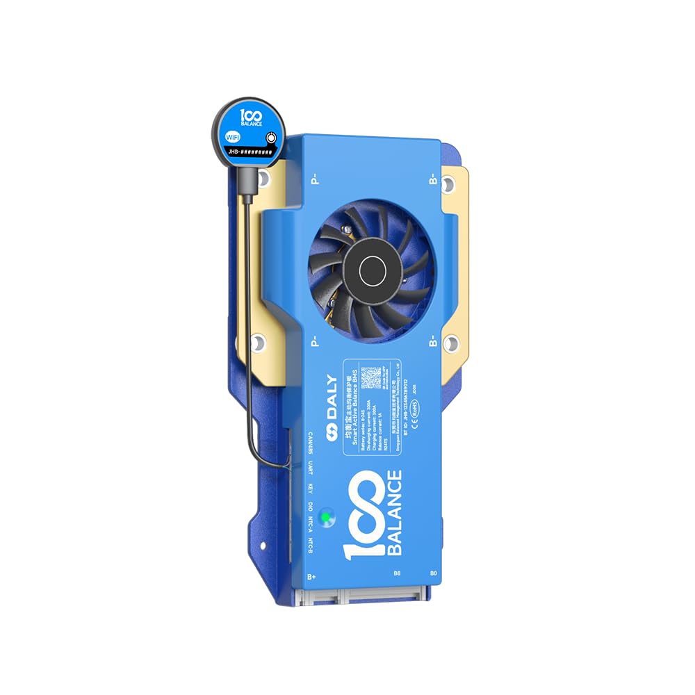
Figure 1: 100BALANCE 300A 8-24S CAN BMS with Wi-Fi module connected.
2. Specifications
The following table details the key product specifications and parameters for the 100BALANCE Smart Active Balance BMS.

Figure 2: Detailed product parameters including charging voltage, discharge current, and protection values.
| Feature | Value |
|---|---|
| Brand | 100 BALANCE |
| Model Number | 300A 8-24S WIFI SET |
| Battery Series | 8-24S |
| Continuous Discharge Current | 300A |
| Max Discharge Current (1s) | 450A |
| Continuous Charge Current | 300A |
| Active Balance Current | 1A |
| Communication Interfaces | Bluetooth, RS485, CAN, Wi-Fi, UART |
| Input Voltage | 100 Volts |
| Color | Blue |

Figure 3: Physical dimensions of different 100BALANCE BMS models, including the 300A variant.
3. Package Contents
Verify that all items listed below are included in your package. If any items are missing or damaged, please contact customer support.
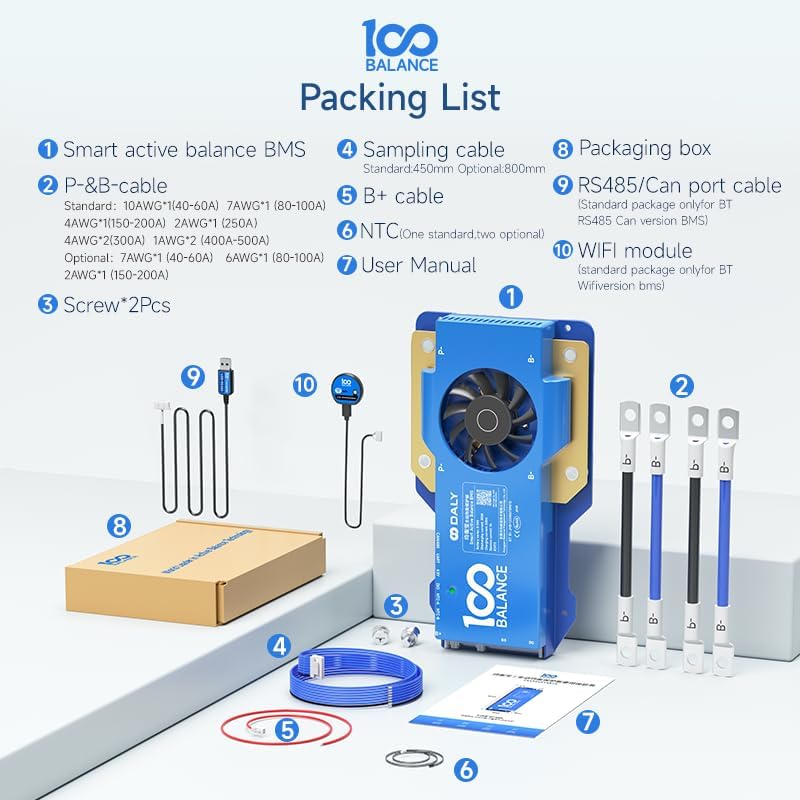
Figure 4: Visual representation of the items included in the standard package.
- Smart Active Balance BMS Unit
- P- & B- Cables (various AWG options available)
- Screws (2 Pcs)
- Sampling Cable (Standard 450mm, Optional 800mm)
- B+ Cable
- NTC Temperature Sensor (One standard, two optional)
- User Manual
- Packaging Box
- RS485/CAN Port Cable (Standard for BT, RS485, CAN versions)
- Wi-Fi Module (Standard package only for BT Wi-Fi version BMS)
4. Setup and Installation
4.1 Battery Pack Wiring Installation
Proper wiring is crucial for the safe and effective operation of the BMS. Always ensure the battery pack is fully discharged before beginning installation. Follow the wiring sequence strictly to prevent damage to the BMS.
- Identify the total positive and total negative terminals of your battery pack.
- Connect the black wire of the sampling cable to the total negative terminal of the battery pack.
- Connect the red wire of the sampling cable to the positive terminal of the first cell, and continue connecting subsequent wires to each cell's positive terminal in sequence.
- Ensure all wires are soldered securely and in the correct order before plugging the sampling cable into the BMS.
- Use a multimeter to verify the voltage consistency across the wiring harness before connecting to the BMS.
- Plug the NTC cable into the NTC-A port on the BMS.
- Connect the B- cable to the total negative terminal of the battery pack and insert the sampling wire into the BMS.
Important Safety Note:
- Miswiring protection is limited to 6 strings. Incorrect wiring for more than 6 strings will damage your BMS.
- Always follow the wiring sequence strictly. If the wiring sequence is reversed, it will lead to BMS damage.

Figure 5: BMS port definitions for CAN/485, KEY, NTC-A, and NTC-B.
5. Operating Instructions
5.1 Wi-Fi Module Usage
The Wi-Fi module enables remote monitoring of your battery pack. Follow these steps to set up and use the Wi-Fi module:
- Connect the Wi-Fi module to the designated port on the BMS.
- Download the "BalanceBMS" app from your iOS or Android app store.
- Ensure your mobile phone is connected to a 2.4GHz Wi-Fi network near the battery pack.
- Open the BalanceBMS app, register an account, and log in.
- In the app, select "Remote monitoring" and follow the prompts to discover and connect to your Wi-Fi module.
- Enter your Wi-Fi password to configure the network.
- Once connected, you can view real-time battery information and status displays, and adjust parameters remotely.

Figure 6: Overview of the Wi-Fi module's remote monitoring capabilities via cloud server and mobile app.

Figure 7: Detailed steps for Wi-Fi module setup and app installation.

Figure 8: Screenshots of the BalanceBMS mobile application, showing local and remote monitoring options and data display.
5.2 PC Host Software Usage
The PC Host software allows for detailed monitoring, parameter setting, and firmware upgrades for your BMS.
- Download PC Host: Visit the official website (www.100balancebms.com) and navigate to the 'Service' -> 'Download' -> 'Application program download' section to download the 100Balance PC Host software. Alternatively, contact customer service for a direct download link.
- Connect PC Host:
- Connect the UART cable (or RS485/CAN cable depending on your BMS model) to the BMS and the other end to your PC.
- Open the PC Host folder and double-click the executable to launch the software.
- In the PC Host software, click "Connection" in the upper right box.
- If using UART or RS485, select the correct COM port and set the baud rate to 9600. If using CAN communication, select CAN and set the baud rate to 250. Click "Open".
- Main Page View:
- On the "Live Data" screen, you can view real-time battery data including total battery voltage, current, temperature, SOC, cell voltage, MOS temperature, and environmental status.
- To modify parameters, click the "Manage" button on the "Live Data" screen, enter the default password (20211115), and then go to the "Set Parameter" page. Here you can set balance current, sleep time, rated capacity, and protection parameters.
- In the "Engineering" interface, you can calibrate the current for more accurate data display.
- To view battery alarm information, go to the "His Data" page and click "Read Historical Faults". You can also clear history data.
- For BMS firmware upgrades, go to the "BMS Upgrade" page, click "Load File" to select the corresponding firmware file, and then click "Start upgrade".
Video 1: Instructions on how to use the Wi-Fi module with your 100Balance BMS for remote monitoring.
Video 2: Tutorial on connecting the 100Balance Smart BMS to the PC host software for advanced configuration and monitoring.
6. Accessories
The 100BALANCE BMS supports various accessories to enhance functionality and monitoring. These can be selected based on your specific needs.
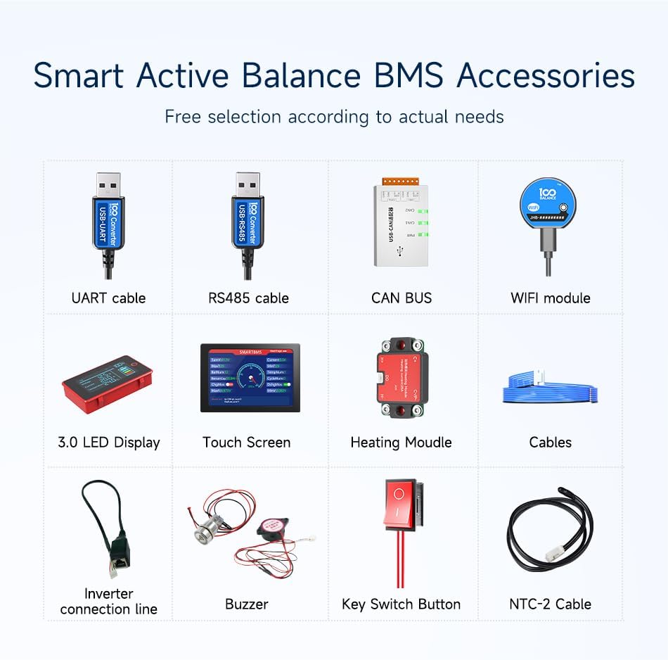
Figure 9: Overview of available accessories for the 100BALANCE BMS.
| Accessory | Description / Function | Connection Type |
|---|---|---|
| UART Cable | For PC connection only. Does not support other equipment. | UART |
| RS485 Cable | For PC connection and other RS485 compatible devices. | RS485 |
| CAN BUS | For CAN communication with compatible devices. | CAN |
| Wi-Fi Module | Enables remote monitoring via mobile app and cloud server. | Dedicated Port |
| 3.0 LED Display | Displays real-time battery information. | UART |
| Touch Screen (4.3 inch) | Advanced display for real-time data and parameter changes. | UART / RS485 |
| Heating Module | Used in cold environments to start the BMS. | Dedicated Port |
| Inverter Connection Line | Direct connection to compatible inverters. | Dedicated Port |
| Buzzer | Provides audible alerts for system status or alarms. | Dedicated Port |
| Key Switch Button | Used to switch on/off discharge MOSFET and other customizable functions. | Dedicated Port |
| NTC-2 Cable | Additional temperature sensor. | NTC-B Port |

Figure 10: Different BMS configurations with optional accessories like Wi-Fi module, LCD display, and inverter cable.
7. Maintenance and Troubleshooting
7.1 Battery Pack Parallel Connection Precautions
When connecting multiple battery packs in parallel, observe the following precautions:
- Ensure the battery voltage is the same in each group before connecting in parallel.
- The voltage difference between parallel battery packs should be less than 1 volt.
- To prevent the battery pack from triggering BMS short circuit protection by high current during parallel connection, manually disconnect the discharging MOSFET in the Bluetooth APP or PC software before connecting.
7.2 Balancing Conditions
The active balancing function is triggered under specific conditions:
- Balancing is initiated when cells reach the open voltage (e.g., 3.000V by default).
- A voltage difference between cells (e.g., 0.01V by default) will also trigger balancing.
7.3 SOC Calibration
For accurate State of Charge (SOC) readings, the BMS can be calibrated:
- The BMS will be calibrated to 100% SOC when a single cell overvoltage protection level 2 is triggered.
8. Warranty and Support
100BALANCE provides a 1-year product warranty for this Smart Active Balance BMS. For any inquiries or technical assistance, our 24/7 online professional service is available to help you. Please feel free to contact us through the official website or your purchase platform.