Introduction
This instruction manual provides essential information for the safe and effective installation, operation, and maintenance of your YC Yier Complete 40" Rear Axle Kit with 8" Wheels and 72V 1500W Motor Controller Differential Kit. This kit is designed for electric vehicle conversion projects, including go-karts, golf carts, tricycles, ATVs, and similar applications. Please read this manual thoroughly before beginning any work to ensure proper assembly and safe usage.
Safety Information
- Electrical Safety: Always disconnect power before making any electrical connections or performing maintenance. Ensure all wiring is correctly insulated and secured to prevent short circuits. Use appropriate personal protective equipment (PPE) when working with electrical components.
- Mechanical Safety: Securely mount all components. Ensure all fasteners are tightened to the manufacturer's specifications. Use appropriate tools and lifting equipment when handling heavy components like the axle and motor.
- Battery Handling: Handle batteries with care. Avoid short-circuiting battery terminals. Ensure proper ventilation when charging batteries.
- Professional Installation: If you are unsure about any part of the installation process, seek assistance from a qualified professional.
Package Contents
Verify that all components listed below are present and undamaged before proceeding with installation.

Figure 1: Overview of all components included in the YC Yier Complete 40" Rear Axle Kit.
- 2x Rear Axle
- 1x 72V 1500W Brushless Motor
- 1x 72V Speed Controller
- 1x Brushless Wiring Harness
- 1x Ignition Key Switch
- 1x 3 Speed Switch
- 1x Throttle Pedal
- 1x Brake Switch
- 1x Charging Port
- 1x Terminal Block
- 1x Forward/Reverse Switch
- 1x LCD Display
- 1x Rear Foot Brake Caliper
- 6x 12V 12Ah Sealed Lead Acid Battery
- 1x 72V Battery Charger
- 5x Battery Cables
- 2x 18x9.50-8 Wheel Tires
Setup and Installation
This section outlines the general steps for assembling and installing the kit components. Specific mounting points and frame modifications will depend on your vehicle's design.
1. Axle Assembly and Mounting
- Mount the rear axle securely to your vehicle's frame. Ensure it is centered and aligned. Refer to the axle dimensions for proper fitment.
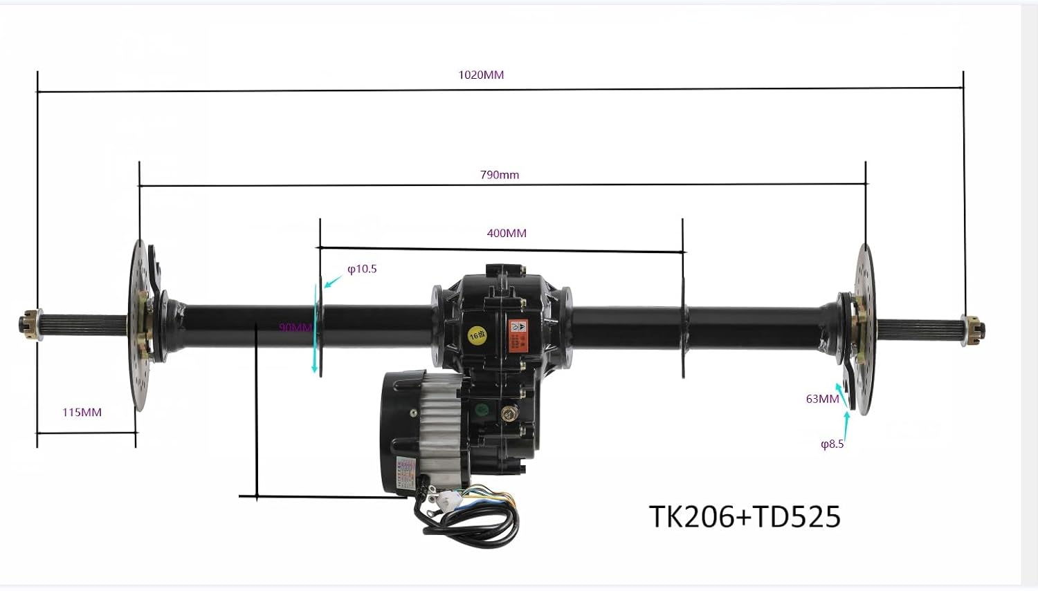
Figure 2: Rear Axle Dimensions (TK206+TD525).
- Attach the brake discs and wheel hubs to the axle shafts. Secure with the provided fasteners.

Figure 3: Axle Shafts with Brake Discs and Hubs.
2. Motor and Differential Installation
- Mount the 72V 1500W brushless motor to the differential housing. Ensure all mounting bolts are securely fastened.
- Attach the motor and differential assembly to the rear axle. The differential allows wheels on the same axle to rotate at different speeds, which is crucial for turning.

Figure 4: Motor and Differential Assembly.
For a visual guide on differential axle installation, you may refer to external resources such as: https://youtu.be/RoZE1SYAxHo
3. Wheel and Tire Installation
- Mount the 18x9.50-8 tires onto the 8-inch rims.
- Attach the assembled wheels to the 4-stud pattern wheel hubs on the axle. Ensure lug nuts are tightened to the appropriate torque specifications.
4. Electrical Wiring
Connect the various electrical components according to the wiring harness diagram. Pay close attention to polarity and ensure all connections are secure.

Figure 5: Controller Wiring Diagram.
- Connect the 72V speed controller to the motor and the main wiring harness.
- Install the ignition key switch, 3-speed switch, throttle pedal, brake switch, forward/reverse switch, and LCD display in accessible locations on your vehicle.
- Connect the rear foot brake caliper to the brake switch.
5. Battery Installation and Connection
- Install the six 12V 12Ah batteries in a secure, well-ventilated location.
- Connect the batteries in series using the provided battery cables to achieve the required 72V system voltage. Ensure correct polarity for each connection.
- Connect the battery pack to the main wiring harness via the terminal block and charging port.
Operating Instructions
- Pre-Operation Check: Before each use, inspect all connections, tire pressure, and brake functionality. Ensure batteries are adequately charged.
- Starting the Vehicle: Insert the key into the ignition switch and turn it to the 'ON' position. The LCD display should illuminate.
- Speed Control: Use the throttle pedal to control the vehicle's speed. The 3-speed switch allows you to select different maximum speed modes.
- Direction Control: Use the forward/reverse switch to select the desired driving direction. Always bring the vehicle to a complete stop before changing direction.
- Braking: Apply the foot brake pedal to engage the rear brake caliper and slow down or stop the vehicle.
- Charging: Connect the 72V battery charger to the charging port when the batteries require recharging. Follow the charger's instructions for safe charging.
Maintenance
- Regular Inspection: Periodically check all electrical connections for tightness and corrosion. Inspect mechanical components for wear, damage, or loose fasteners.
- Battery Care: Keep batteries clean and charged. Avoid deep discharges. Store the vehicle with fully charged batteries if it will not be used for an extended period.
- Tire Maintenance: Maintain correct tire pressure as specified for your application. Inspect tires for wear and damage.
- Brake System: Regularly check the brake caliper and pads for wear. Ensure the brake system operates smoothly and effectively.
- Cleaning: Keep the motor, controller, and other components free from dirt, dust, and moisture.
Troubleshooting
| Problem | Possible Cause | Solution |
|---|---|---|
| Vehicle does not power on | Low battery charge, loose battery connection, faulty ignition switch, controller issue | Check battery charge and connections. Test ignition switch. Inspect controller wiring. |
| Motor not running | Throttle issue, motor wiring, controller fault, brake switch engaged | Verify throttle operation. Check motor and controller wiring (Figure 5). Ensure brake switch is not stuck. |
| Inconsistent speed | Loose electrical connections, faulty throttle, controller issue | Inspect all wiring connections. Test throttle pedal. |
| Brakes not effective | Worn brake pads, loose caliper, air in brake line (if hydraulic), misadjusted brake switch | Inspect and replace brake pads if worn. Tighten caliper. Bleed brake line if necessary. Adjust brake switch. |
Specifications
Motor Specifications
- Rated Voltage: 72V
- Rated Power: 1500W
- Max Speed: 4800 RPM
- Rated Speed: 3900 RPM
- Rated Torque: 3.3 N.m
- Max Torque: 28.3 N.m
- Rated Current: 18-35Ah
- Gear Ratio: 9.5:1
- Drive Axle: 16-tooth, high-strength chrome

Figure 6: Motor Dimensions.
Controller Specifications
- Nominal Voltage: 36V / 42V / 48V / 52V / 58V / 60V / 64V / 72V / 84V (Automatic Identification)
- Maximum Current: 45A-60A
- Brake: Low / High Electrical Level
- Motor Phase Angle: Automatic Identification

Figure 7: Controller Specifications Label.
Wheel Specifications
- Tire Size: 18x9.50-8
- Rim Size: 8 inches
- Wheel Height: 18.5 inches (470mm)
- Wheel Width: 8.46 inches (215mm)
- Pattern: 4-bolt, 110mm Spacing

Figure 8: Wheel and Tire Dimensions.
Battery Specifications
- Type: Sealed Lead Acid (SLA)
- Voltage (each): 12V
- Capacity (each): 12Ah
- Quantity: 6 (for 72V system)
- Optimal Performance Power: 12V 12Ah
- Dimensions (each): 5.91" x 3.94" x 3.7" (150mm x 100mm x 95mm)
- Weight (each): 8.8 lbs (3.8kg)

Figure 9: Battery Specifications.
Support
For technical assistance, warranty information, or replacement parts, please contact YC Yier customer support through your original point of purchase or visit the manufacturer's website.