1. Introduction
This manual provides essential information for the safe and efficient operation of your EDRIWYIM 48V/60V/72V 50A 1500W Sine Wave Electric Bike Motor Speed Controller. This intelligent controller is designed to manage the power delivery to your electric bike's motor, ensuring smooth and responsive performance across a range of voltages. Please read this manual thoroughly before installation and use to ensure proper functionality and safety.
2. Safety Instructions
- Always disconnect the battery before performing any installation, maintenance, or wiring adjustments.
- Ensure all connections are secure and properly insulated to prevent short circuits.
- Verify that the controller's voltage rating (48V/60V/72V) matches your electric bike's battery voltage.
- Avoid exposing the controller to water, excessive moisture, or extreme temperatures.
- If you are unsure about any installation steps, seek assistance from a qualified technician.
- Do not attempt to open or modify the controller casing, as this may void the warranty and pose a safety risk.
3. Product Overview
The EDRIWYIM Electric Bike Motor Speed Controller is a high-performance component designed for electric bicycles. It features sine wave technology for smoother motor operation and reduced noise. The robust aluminum alloy casing provides excellent heat dissipation, ensuring stable performance even under demanding conditions.
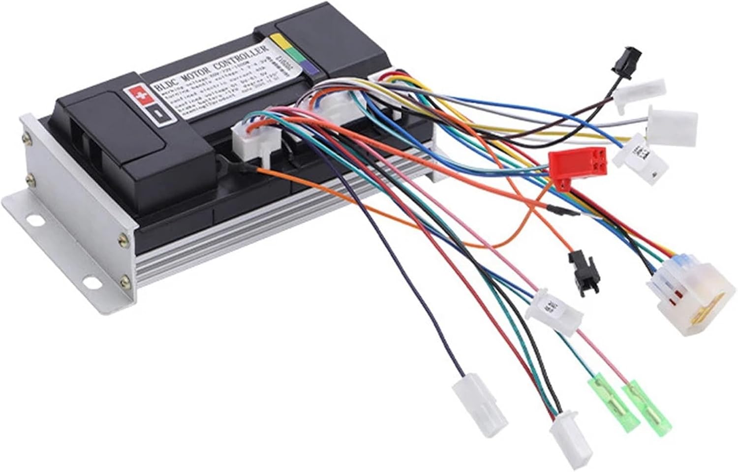
Figure 3.1: Top view of the EDRIWYIM Electric Bike Motor Speed Controller, showing the main unit with multiple colored wire harnesses extending from its side. These harnesses are used for connecting to the motor, battery, throttle, brakes, and other bike components.

Figure 3.2: A closer view of the controller's top surface, highlighting the "BLDC MOTOR CONTROLLER" label and specifications such as working voltage (48V-72V) and rated power (1500W). Various connection ports are also visible.

Figure 3.3: The underside of the controller, featuring prominent aluminum heat sink fins. These fins are crucial for dissipating heat generated during operation, ensuring the controller maintains optimal temperature and performance.
4. Specifications
| Feature | Specification |
|---|---|
| Rated Voltage | 48V / 60V / 72V |
| Rated Current | 50A |
| Rated Power | 1500W |
| Controller Type | Sine Wave Split Intelligent Motor Speed Controller |
| Main Material | Aluminum Alloy |
| Dimensions (Approx.) | 1.18 x 0.79 x 0.39 inches (Package Dimensions) |
| Item Weight (Approx.) | 1.76 ounces |
5. Setup and Installation
Proper installation is crucial for the performance and safety of your electric bike. It is highly recommended that installation be performed by an experienced technician.
5.1. Wiring Diagram (General Guidance)
While a specific wiring diagram is not provided in this manual, electric bike controllers typically involve connections for the following components. Refer to your motor and battery documentation for specific pinouts and color codes.
- Battery Connection: Connect the main positive (+) and negative (-) wires from your battery to the corresponding terminals on the controller. Ensure correct polarity.
- Motor Connection: Connect the three phase wires (U, V, W, typically Green, Blue, Yellow) from the controller to the motor.
- Hall Sensor Wires: Connect the Hall sensor wires (typically 5 small wires: +5V, GND, Ha, Hb, Hc) from the controller to the motor's Hall sensors.
- Throttle Connection: Connect the throttle wires (typically +5V, Signal, GND) to the controller's throttle input.
- Brake Levers: Connect the brake lever wires (typically two wires per lever) to the controller's brake input. These usually cut motor power when activated.
- Display/Meter: If applicable, connect the display unit to the controller.
- Other Functions: Depending on your controller and bike, there may be additional connections for features like pedal assist (PAS), cruise control, anti-theft, etc.
Important: Incorrect wiring can damage the controller, motor, or battery. Double-check all connections before applying power.
6. Operating Instructions
- Power On: Once all connections are secure, turn on your electric bike's battery or main power switch. The controller will typically perform a self-check.
- Throttle Control: Gently twist the throttle to engage the motor. The motor speed will increase proportionally with the throttle input.
- Braking: Activating the brake levers will cut power to the motor, allowing for safe stopping.
- Monitoring: If your bike has a display, monitor battery level, speed, and other relevant information during operation.
7. Maintenance
- Regular Inspection: Periodically check all wiring connections for signs of wear, corrosion, or looseness.
- Cleaning: Keep the controller clean and free from dust, dirt, and debris. Use a dry, soft cloth for cleaning. Do not use water or harsh chemicals.
- Environmental Protection: Ensure the controller is mounted in a location protected from direct water spray and excessive heat.
- Avoid Impact: Protect the controller from physical impact or drops.
8. Troubleshooting
| Problem | Possible Cause | Solution |
|---|---|---|
| Motor does not run | No power to controller; Loose connections; Faulty throttle; Faulty motor Hall sensors. | Check battery connection and charge; Inspect all wiring; Test throttle functionality; Check motor Hall sensor wires. |
| Motor runs intermittently or erratically | Loose Hall sensor connections; Intermittent throttle signal; Overheating. | Secure Hall sensor wires; Check throttle wiring; Allow controller to cool down; Ensure proper ventilation. |
| Controller gets excessively hot | Overload; Insufficient ventilation; Short circuit in motor or wiring. | Reduce load; Ensure controller is mounted in a well-ventilated area; Inspect motor and wiring for shorts. |
| No power to display/accessories | Loose accessory wiring; Blown fuse (if applicable). | Check all accessory connections; Replace fuse if necessary. |
9. Warranty and Support
For warranty information and technical support, please refer to the documentation provided at the time of purchase or contact your retailer. Keep your purchase receipt as proof of purchase.