1. Introduction
The PEAKMETER PM8233B is a compact, handheld digital multimeter designed for accurate electrical measurements. This device features a 3 1/2-digit, 15mm character height LCD display with backlight, enabling clear data readability in various lighting conditions. It is capable of measuring AC and DC voltage, DC current, resistance, and performing diode and continuity tests. This manual provides essential information for the safe and effective use of your PM8233B multimeter.

Image 1.1: Overview of PEAKMETER PM8233 series digital multimeters, including the PM8233B model, showcasing their design and display.
2. Safety Information
To ensure safe operation and avoid damage to the meter, please read and follow all safety instructions carefully. This device complies with safety standards EN61010-1, EN61010-2-033, EN61326, and is rated CAT. III 600V.
- Always ensure the test leads are in good condition and properly connected before making any measurements.
- Do not apply voltage or current that exceeds the maximum specified limits for the selected range.
- Exercise extreme caution when working with voltages above 30V AC RMS, 42V peak, or 60V DC. These voltages pose a shock hazard.
- Before changing functions or ranges, disconnect the test leads from the circuit under test.
- Do not use the meter if it appears damaged or if the case is open.
- Replace the battery immediately when the low battery indicator appears to ensure accurate readings.
- Fuses must be replaced with specified types and ratings only (F 250mA/250V, 10A/250V).
3. Product Overview
3.1 Key Features
- 3 1/2-digit LCD display with 2000 counts.
- Automatic ranging for most measurements.
- Data Hold function to freeze displayed readings.
- Diode Test and Continuity Test functions.
- Backlight for improved visibility in low-light conditions.
- Auto Power Off feature to conserve battery life.
- Overload protection across all ranges.
- Compact, handheld design with a soft rubber protective case.
3.2 Convenience Slot
The PM8233B features a practical slot on the back of its protective case, designed to securely hold the test probes. This design enhances portability and helps prevent the loss of test leads when the multimeter is not in use.

Image 3.1: Rear view of the PM8233B multimeter showing the integrated slot for convenient storage of test probes.

Image 3.2: Detailed view of the test probes securely placed in the back slot of the PM8233B, highlighting the convenience feature.
4. Setup
4.1 Battery Installation
The PM8233B is powered by a DC 9V 6F22 battery. A Lithium Polymer battery is included with the device.
- Ensure the multimeter is turned off and disconnect all test leads.
- Locate the battery compartment cover on the back of the meter.
- Unscrew the retaining screw(s) and remove the cover.
- Connect the 9V battery to the battery connector, observing correct polarity.
- Place the battery into the compartment and replace the cover, securing it with the screw(s).
Note: Replace the battery when the low battery indicator appears on the display to maintain measurement accuracy.
5. Operating Instructions
Before operating, ensure the battery is installed correctly and the test leads are securely connected to the appropriate input jacks.
5.1 Measuring DC Voltage
- Insert the red test lead into the "VΩmA" jack and the black test lead into the "COM" jack.
- Turn the rotary switch to the desired DC Voltage (V=) range (e.g., 200mV, 2V, 20V, 200V, 600V). If the voltage is unknown, start with the highest range and decrease as necessary.
- Connect the test probes across the component or circuit to be measured, observing polarity.
- Read the voltage value on the display.

Image 5.1: The PM8233B multimeter connected to a circuit for DC voltage measurement, displaying the reading.
5.2 Measuring AC Voltage
- Insert the red test lead into the "VΩmA" jack and the black test lead into the "COM" jack.
- Turn the rotary switch to the desired AC Voltage (V~) range (e.g., 200V, 600V).
- Connect the test probes across the AC voltage source or circuit.
- Read the voltage value on the display.

Image 5.2: The PM8233B multimeter connected to an AC power source for AC voltage measurement, showing the displayed value.
5.3 Measuring DC Current
- For currents up to 200mA, insert the red test lead into the "VΩmA" jack. For currents up to 10A, insert the red test lead into the "10A" jack. The black test lead always goes into the "COM" jack.
- Turn the rotary switch to the desired DC Current (A=) range (e.g., 200µA, 2mA, 20mA, 200mA, 10A).
- Important: To measure current, the meter must be connected in series with the circuit. Open the circuit and insert the meter.
- Read the current value on the display.
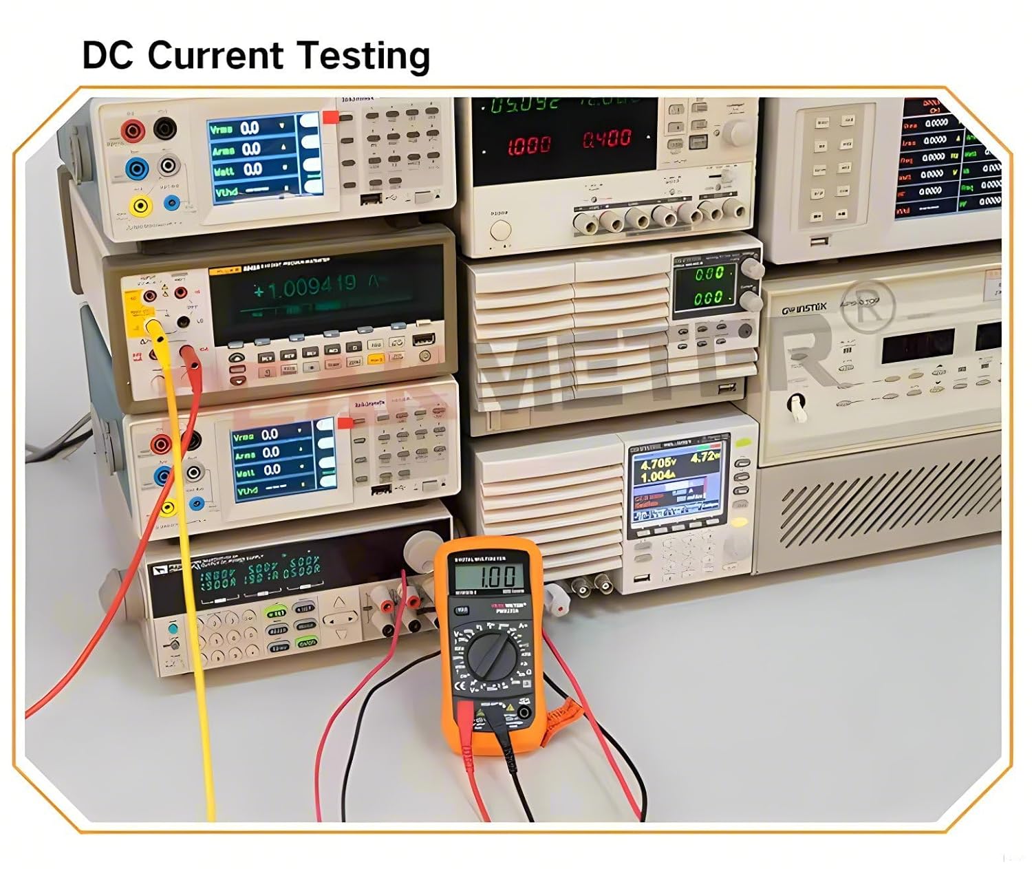
Image 5.3: The PM8233B multimeter configured for DC current measurement, connected in series within a circuit.
5.4 Measuring Resistance
- Insert the red test lead into the "VΩmA" jack and the black test lead into the "COM" jack.
- Turn the rotary switch to the Resistance (Ω) range (e.g., 200Ω, 2kΩ, 20kΩ, 200kΩ, 2MΩ).
- Ensure the circuit or component under test is de-energized before measuring resistance.
- Connect the test probes across the resistor or component.
- Read the resistance value on the display.

Image 5.4: The PM8233B multimeter measuring the resistance of a component, showing the reading on the display.
5.5 Diode Test
- Insert the red test lead into the "VΩmA" jack and the black test lead into the "COM" jack.
- Turn the rotary switch to the Diode Test (→|) position.
- Connect the red probe to the anode and the black probe to the cathode of the diode.
- A forward voltage drop (typically 0.5V to 0.8V for silicon diodes) will be displayed. Reverse the probes; the display should show "OL" (Open Loop) for a good diode.
5.6 Continuity Test
- Insert the red test lead into the "VΩmA" jack and the black test lead into the "COM" jack.
- Turn the rotary switch to the Continuity Test (♫) position.
- Connect the test probes across the circuit or component.
- If the resistance is below approximately 50Ω, the buzzer will sound, indicating continuity. The display will also show the resistance value.
5.7 Data Hold Function
Press the "HOLD" button to freeze the current reading on the display. Press it again to release the hold and resume live measurements.
5.8 Backlight
The backlight can be activated by pressing the "Backlight" button (often combined with HOLD or a dedicated button). This improves visibility in dimly lit environments.
5.9 Auto Power Off
The meter features an automatic power-off function to conserve battery life. If no operation is performed for approximately 15 minutes, the meter will automatically shut down. To reactivate, turn the rotary switch to OFF and then back to the desired function, or press any button.
6. Maintenance
6.1 Cleaning
Wipe the case with a damp cloth and a mild detergent. Do not use abrasives or solvents. Ensure the meter is completely dry before use.
6.2 Battery Replacement
Refer to Section 4.1 for detailed instructions on replacing the 9V 6F22 battery.
6.3 Fuse Replacement
If the current measurement function fails, the fuse may need replacement. Always replace fuses with the specified type and rating to maintain safety and performance.
- F1 Fuse: F 250mA/250V (for mA ranges)
- F2 Fuse: 10A/250V (for 10A range)
- Ensure the multimeter is turned off and disconnect all test leads.
- Open the battery compartment cover as described in Section 4.1.
- Carefully remove the old fuse(s) and replace with new ones of the correct rating.
- Replace the battery compartment cover and secure it.
7. Troubleshooting
- No display or faint display: Check battery installation. Replace battery if low battery indicator is on or if display is faint.
- Incorrect readings:
- Ensure correct function and range are selected.
- Verify test leads are properly connected and not damaged.
- Check battery level.
- Current measurement not working: Check the fuse(s) as described in Section 6.3. Ensure the meter is connected in series with the circuit.
- "OL" displayed: This indicates an overload or an open circuit, depending on the function. For resistance, it means the resistance is higher than the selected range. For diode test, it indicates a reverse-biased good diode.
8. Specifications
| Measurement | Range | Accuracy |
|---|---|---|
| DC Voltage | 200mV/2V/20V/200V | ±(0.5%+2) |
| 600V | ±(0.8%+2) | |
| AC Voltage | 200V/600V | ±(1.2%+10) |
| DC Current | 200µA/2mA/20mA | ±(1.0%+2) |
| 200mA | ±(1.5%+2) | |
| 10A | ±(3.0%+2) | |
| Resistance | 200Ω/2kΩ/20kΩ/200kΩ | ±(0.8%+2) |
| 2MΩ | ±(1.0%+2) |
General Specifications
- Display: 2000 counts, 3 1/2-digit LCD
- Measuring Method: Dual-slope integration A/D converter
- Power Supply: DC 9V (6F22 battery)
- Fuse Protection: F 250mA/250V (for mA), 10A/250V (for 10A)
- Safety Rating: EN61010-1, 61010-2-033, EN61326, CAT. III 600V
- Operating Temperature: 0°C to 40°C (32°F to 104°F)
- Storage Temperature: -10°C to 50°C (14°F to 122°F)
- Dimensions: Approximately 148mm x 74mm x 42mm
- Net Weight: Approximately 173g (battery not included)
- Color: Orange
- Included Components: EC-PM8233B, Test Leads, 9V Battery
9. Warranty and Support
For warranty information and technical support, please refer to the documentation provided with your purchase or contact PEAKMETER customer service. Keep your purchase receipt as proof of purchase.