1. Introduction
The PEAKMETER PM8233E is a smart pocket handheld digital multimeter designed for measuring DC and AC voltage, DC and AC current, resistance, frequency, and temperature. It features a 2000-count display, data hold, diode test, and continuity functions, making it a versatile tool for electrical testing and troubleshooting. This manual provides essential information for safe and effective operation of your device.
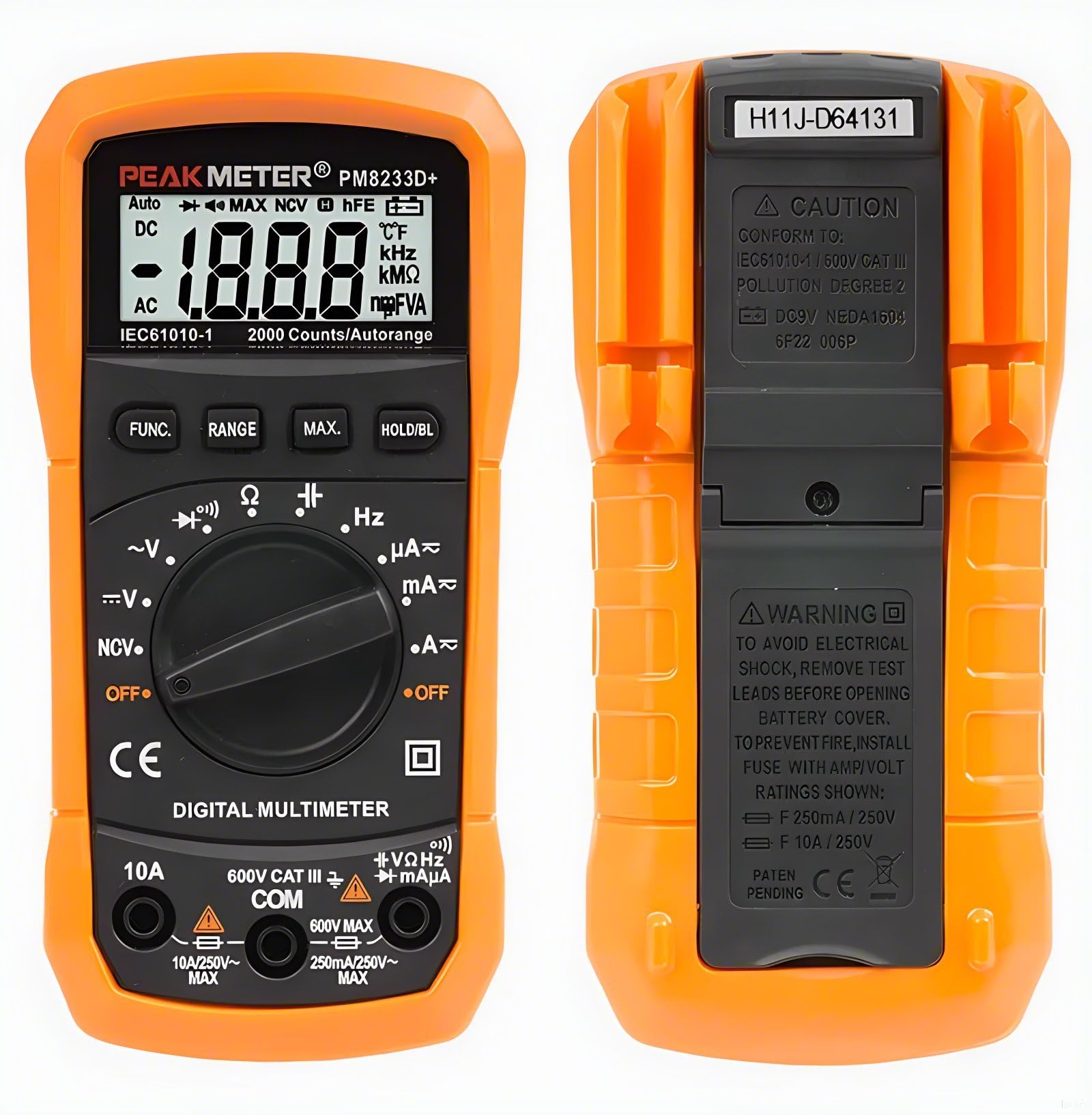
Figure 1: PEAKMETER PM8233E Digital Multimeter
2. Safety Information
WARNING: To avoid electrical shock, remove test leads before opening the battery cover. To prevent fire, install fuses with the specified Amp/Volt ratings: F 250mA / 250V and F 10A / 250V.
This device conforms to IEC61010-1 / 600V CAT III, Pollution Degree 2 standards. Always adhere to the following safety precautions:
- Do not exceed the maximum input values specified for each measurement range.
- Use caution when working with voltages above 30V AC RMS, 42V peak, or 60V DC, as these pose a shock hazard.
- Ensure the test leads are in good condition and properly connected before making any measurements.
- Never use the multimeter if it appears damaged or if the protective casing is compromised.
- Always turn off the device and disconnect test leads before replacing batteries or fuses.
- Do not operate the multimeter in explosive atmospheres or in the presence of flammable gases or dust.

Figure 2: Back of the Multimeter with Safety Warnings
3. Package Contents
Verify that all items are present in your package:
- PEAKMETER PM8233E Digital Multimeter
- Test Leads
- User Manual

Figure 3: Package Contents
4. Product Features and Components
The PM8233E multimeter is designed for ease of use and durability. Key components include:
- LCD Display: Large 3 1/2 digit display for clear readings.
- Rotary Switch: Selects measurement functions and ranges.
- Function Buttons: For Data Hold, Range, Max Value, and Backlight.
- Input Jacks: For connecting test leads (COM, VΩmA, 10A).
- Protective Rubber Case: Provides protection against impacts.
- Support Frame: Integrated kickstand for hands-free operation.
- Test Probe Convenience Slot: Located on the back for easy storage of test leads.

Figure 4: Multimeter Components (LCD, Battery Jar, Support Frame)

Figure 5: Test Probe Convenience Slot
5. Setup
5.1 Battery Installation
- Ensure the multimeter is turned off and test leads are disconnected.
- Locate the battery compartment on the back of the device.
- Unscrew the battery cover and remove it.
- Insert a new 9V 6F22 battery, observing the correct polarity.
- Replace the battery cover and secure it with the screw.
6. Operating Instructions
Before any measurement, ensure the test leads are correctly inserted into the appropriate input jacks (COM and VΩmA for most measurements, 10A for high current). Always select the correct function using the rotary switch.
6.1 AC/DC Voltage Measurement
- Set the rotary switch to the desired AC V (~) or DC V (---) range.
- Connect the black test lead to the COM jack and the red test lead to the VΩmA jack.
- Connect the test probes in parallel to the circuit or component under test.
- Read the voltage value on the display.
6.2 DC Current Measurement
- Set the rotary switch to the desired DC A (---) range (e.g., 200µA, 2mA, 20mA, 200mA, 10A).
- For currents up to 200mA, connect the red test lead to the VΩmA jack. For currents up to 10A, connect the red test lead to the 10A jack. The black test lead always connects to COM.
- Open the circuit and connect the test probes in series with the circuit or component.
- Read the current value on the display.
6.3 Resistance Measurement
- Set the rotary switch to the Ω (Ohms) range.
- Connect the black test lead to the COM jack and the red test lead to the VΩmA jack.
- Ensure the circuit is de-energized before measuring resistance.
- Connect the test probes across the component to be measured.
- Read the resistance value on the display.
6.4 Continuity Test
- Set the rotary switch to the continuity (speaker icon) range.
- Connect the black test lead to the COM jack and the red test lead to the VΩmA jack.
- Connect the test probes across the circuit or component.
- If the resistance is below approximately 50Ω, the buzzer will sound, indicating continuity.
6.5 Diode Test
- Set the rotary switch to the diode (arrow with line) range.
- Connect the black test lead to the COM jack and the red test lead to the VΩmA jack.
- Connect the red test probe to the anode and the black test probe to the cathode of the diode.
- The display will show the forward voltage drop. Reverse the probes; the display should show 'OL' (Open Loop) for a good diode.
6.6 Data Hold Function
Press the HOLD button to freeze the current reading on the display. Press it again to release the hold and resume live readings.
6.7 Backlight
Press the BACKLIGHT button to turn on the display backlight for better visibility in low-light conditions. Press it again to turn it off.
6.8 Auto Ranging
The PM8233E features auto-ranging, which automatically selects the appropriate measurement range. For specific applications, manual ranging might be available by pressing the RANGE button (refer to specific model features).
6.9 Operational Demonstrations
Video 1: Demonstration of AC voltage, DC voltage, capacitance, and DC current measurements using a PEAKMETER multimeter.
7. Maintenance
7.1 Cleaning
Wipe the case with a damp cloth and mild detergent. Do not use abrasives or solvents. Keep the input terminals free of dirt and moisture.
7.2 Battery Replacement
When the battery low indicator appears on the display, replace the 9V battery as described in Section 5.1.
7.3 Fuse Replacement
If the current measurement function fails, the fuse may need replacement. Refer to the safety warnings in Section 2 for fuse specifications (F 250mA / 250V and F 10A / 250V). Fuse replacement should only be performed by qualified personnel.
8. Troubleshooting
- No Display: Check battery installation and charge level. Replace battery if necessary.
- Incorrect Readings: Ensure test leads are properly connected and the correct function/range is selected. Verify the circuit is de-energized for resistance measurements.
- Current Measurement Not Working: Check the fuse. If blown, replace with the correct rating.
- 'OL' on Display: Indicates an open circuit or a value exceeding the selected range.
9. Specifications
The following table outlines the specifications for the PEAKMETER PM8233E Digital Multimeter:
| Measurement | Range | Accuracy (PM8233E) |
|---|---|---|
| DC Voltage | 200mV/2V/20V/200V/600V | ±(0.5%+2) |
| AC Voltage | 2V/20V/200V/600V | ±(0.8%+2) |
| DC Current | 200µA/2mA/20mA/200mA/10A | ±(1.0%+3) (200µA-200mA), ±(3.0%+5) (10A) |
| AC Current | 200µA/2mA/20mA/200mA/10A | ±(1.2%+3) (200µA-200mA), ±(3.0%+5) (10A) |
| Resistance | 200Ω/2kΩ/20kΩ/200kΩ/2MΩ/20MΩ | ±(0.8%+2) (200Ω-2MΩ), ±(1.0%+2) (20MΩ) |
| Frequency | 20kHz | ±(1.0%+2) |
| Temperature | -20 ~ 1000°C | ±(3.0%+3) |
General Features:
- Display: 2000 counts
- Auto Range: Yes
- Data Hold: Yes
- Backlight: Yes
- Diode Test: Yes
- Continuity: Yes
- Maximum Value Hold: Yes
- Power Supply: DC9V 6F22 battery
- Weight: Approx. 110g
- Size: 140 x 67 x 30mm
- Safety Rating: EN61010-1, -2-030, EN61010-2-033, EN61326, CAT.III 600V
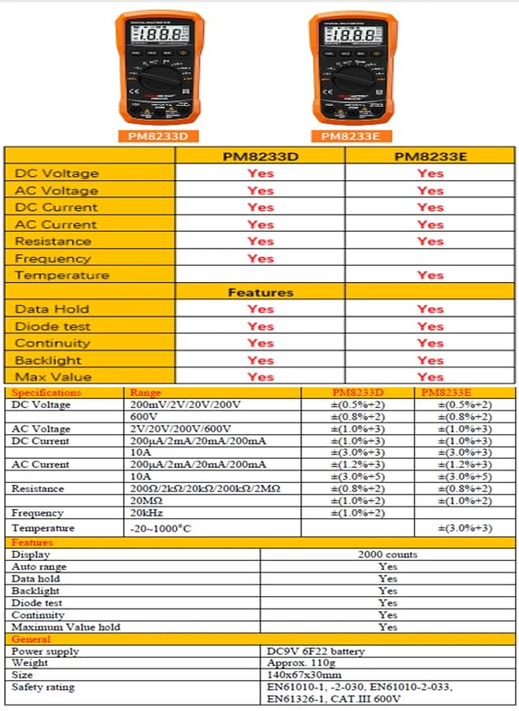
Figure 6: Detailed Specifications for PM8233E
10. Warranty and Support
The PEAKMETER PM8233E Digital Multimeter comes with a 1-year warranty from the date of purchase. For technical support or warranty claims, please contact your retailer or the manufacturer directly. Keep your purchase receipt as proof of purchase.


