1. Introduction
The PEAKMETER PM8237 is a high-precision, autoranging digital multimeter designed for professional and home use. It features a 30000-count display with automatic unit symbol indication, True RMS measurement capabilities, and a USB interface for data logging. This manual provides essential information for the safe and effective operation of your PM8237 multimeter.
Key features include:
- 30000 Counts Display with Digital and Analog Bar Graph
- True RMS (TRMS) Measurement
- Measures AC/DC Voltage, AC/DC Current, Resistance, Capacitance, Frequency, Duty Cycle, Diode, Continuity, hFE, and NCV (Non-Contact Voltage)
- USB Interface for PC Connectivity
- Low Pass Filter (LPF) for accurate AC measurements
- MAX/MIN, Data Hold, and Relative Measurement functions
- Automatic Power Off and Low Battery Indication
- Over-range indication: “OL” is displayed
- Backlight for improved visibility in dim conditions

Image 1.1: The PM8237 multimeter highlighting its comprehensive range of functions, including AC/DC Voltage, Current, Resistance, Capacitance, Frequency, Diode, Continuity, HFE, USB Interface, Auto Power Off, and Auto Range.
2. Safety Information
To ensure safe operation and avoid damage to the meter, please read and follow all safety instructions carefully. This device complies with EN61010-1, EN61010-2-033, EN61326, CAT.Ⅲ 1000V/CAT.Ⅳ 600V safety standards.
General Safety Precautions:
- Always inspect the test leads for damage (cracks, breaks) before use. Do not use if damaged.
- Do not apply voltage or current that exceeds the maximum rated value for the selected range. The maximum voltage allowed between measurement ends and earth is 1000V DC or 1000V AC RMS.
- Ensure the function switch is in the correct position for the measurement you intend to make.
- Be extremely cautious when working with high voltages. Avoid contact with live circuits.
- Replace batteries promptly when the low battery indicator appears to ensure accurate readings.
- Do not operate the meter if it appears damaged or if the case is open.
- Use the meter only as specified in this manual; otherwise, the protection provided by the meter may be impaired.
- Before measuring current, ensure the circuit power is off and the test leads are connected in series with the circuit.
- When measuring resistance, capacitance, or diode, ensure the circuit under test is de-energized and all capacitors are discharged.
3. Product Overview
Familiarize yourself with the components and controls of your PM8237 Digital Multimeter.
3.1 Front Panel Layout
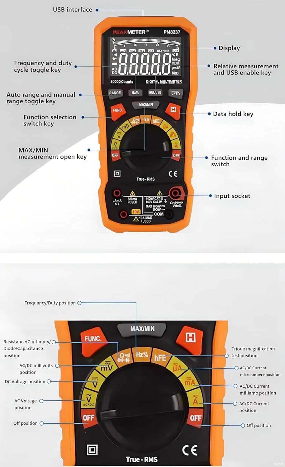
Image 3.1: Detailed diagram of the PM8237's front panel, indicating the display, USB interface, function keys, rotary switch, and input sockets.
- Display: 30000-count LCD with backlight and analog bar graph.
- USB Interface: For connecting to a computer for data transfer.
- RANGE Button: Toggles between auto range and manual range.
- Hz% Button: Selects frequency or duty cycle measurement.
- REL/USB Button: Activates relative measurement mode or enables USB communication.
- LPF Button: Activates Low Pass Filter for AC voltage/current measurements.
- MAX/MIN Button: Records maximum and minimum values.
- FUNC Button: Selects different functions within a single rotary switch position (e.g., AC/DC, Diode/Continuity).
- HOLD Button: Freezes the current display reading.
- Rotary Switch: Selects the main measurement function (e.g., Voltage, Current, Resistance).
- Input Sockets:
- COM: Common terminal for all measurements.
- VΩHz: Input for Voltage, Resistance, Frequency, Capacitance, Diode, Continuity, Temperature, NCV.
- mAµA: Input for milliampere and microampere current measurements.
- 10A: Input for 10 Ampere current measurements.
3.2 Dimensions

Image 3.2: Physical dimensions of the PM8237 multimeter, measuring 204mm (L) x 94mm (W) x 57mm (H).
4. Setup
4.1 Battery Installation
The PM8237 requires four 1.5V AA batteries for operation. The battery compartment is located on the back of the meter.
- Ensure the multimeter is turned OFF.
- Locate the battery compartment cover on the back of the unit.
- Use a screwdriver to loosen the screw(s) securing the cover.
- Remove the cover.
- Insert four 1.5V AA batteries, observing the correct polarity (+ and -) as indicated inside the compartment.
- Replace the battery compartment cover and tighten the screw(s).

Image 4.1: The PM8237 multimeter shown with its carrying case and the four AA batteries required for operation.
4.2 Connecting Test Leads
Always connect the black test lead to the COM input jack. Connect the red test lead to the appropriate input jack based on the measurement type:
- VΩHz: For voltage, resistance, frequency, capacitance, diode, continuity, and temperature measurements.
- mAµA: For current measurements up to 300mA.
- 10A: For current measurements up to 10A.
5. Operating Instructions
This section details how to perform various measurements with your PM8237 multimeter.
5.1 DC Voltage Measurement (V–)
- Insert the black test lead into the COM jack and the red test lead into the VΩHz jack.
- Turn the rotary switch to the V– position.
- Connect the test leads across the DC voltage source or component to be measured.
- Read the voltage value on the display.
5.2 AC Voltage Measurement (V∼)
- Insert the black test lead into the COM jack and the red test lead into the VΩHz jack.
- Turn the rotary switch to the V∼ position.
- Connect the test leads across the AC voltage source or component to be measured.
- Read the voltage value on the display. Press the LPF button for measurements in noisy environments.

Image 5.1: Examples of common measurements: DC Voltage, Resistance, Diode Test, DC mA, and DC Ampere.
5.3 DC Current Measurement (A–, mA–, µA–)
- Turn off power to the circuit.
- Insert the black test lead into the COM jack.
- For currents up to 300mA, insert the red test lead into the mAµA jack. For currents up to 10A, insert the red test lead into the 10A jack.
- Turn the rotary switch to the appropriate A–, mA–, or µA– position.
- Break the circuit and connect the test leads in series with the circuit.
- Restore power to the circuit and read the current value.
5.4 AC Current Measurement (A∼, mA∼, µA∼)
- Follow steps 1-5 for DC Current Measurement, but turn the rotary switch to the appropriate A∼, mA∼, or µA∼ position.
- Read the current value. Press the LPF button for measurements in noisy environments.
5.5 Resistance Measurement (Ω)
- Ensure the circuit is de-energized and all capacitors are discharged.
- Insert the black test lead into the COM jack and the red test lead into the VΩHz jack.
- Turn the rotary switch to the Ω position.
- Connect the test leads across the component to be measured.
- Read the resistance value.
5.6 Capacitance Measurement (F)
- Ensure the capacitor is fully discharged before measurement.
- Insert the black test lead into the COM jack and the red test lead into the VΩHz jack.
- Turn the rotary switch to the F position.
- Connect the test leads across the capacitor.
- Read the capacitance value.
5.7 Frequency and Duty Cycle Measurement (Hz%)
- Insert the black test lead into the COM jack and the red test lead into the VΩHz jack.
- Turn the rotary switch to the Hz% position.
- Connect the test leads across the signal source.
- Press the Hz% button to toggle between frequency and duty cycle display.
5.8 Diode Test (→|•))
- Ensure the circuit is de-energized.
- Insert the black test lead into the COM jack and the red test lead into the VΩHz jack.
- Turn the rotary switch to the →|•)) position.
- Press the FUNC button to select Diode Test.
- Connect the red test lead to the anode and the black test lead to the cathode of the diode.
- Read the forward voltage drop. Reverse the leads to check for open circuit (OL).
5.9 Continuity Test (•))
- Ensure the circuit is de-energized.
- Insert the black test lead into the COM jack and the red test lead into the VΩHz jack.
- Turn the rotary switch to the →|•)) position.
- Press the FUNC button to select Continuity Test.
- Connect the test leads across the circuit or component. A continuous beep indicates continuity (low resistance).
5.10 hFE Measurement
- Insert the black test lead into the COM jack and the red test lead into the VΩHz jack.
- Turn the rotary switch to the hFE position.
- Insert the transistor leads (E, B, C) into the corresponding hFE socket holes on the meter.
- Read the hFE value on the display.
5.11 Non-Contact Voltage (NCV) Detection
- Turn the rotary switch to the NCV position.
- Move the top end of the multimeter near a live AC voltage source.
- The meter will emit an audible beep and the NCV indicator will light up, indicating the presence of AC voltage.
5.12 Special Functions
- Auto/Manual Ranging: The meter defaults to auto-ranging. Press the RANGE button to switch to manual ranging. In manual ranging, press RANGE repeatedly to cycle through available ranges.
- Data Hold: Press the HOLD button to freeze the current reading on the display. Press again to release.
- MAX/MIN: Press the MAX/MIN button to enter MAX/MIN recording mode. The meter will display the maximum or minimum value measured since activation. Press again to cycle between MAX, MIN, and current reading.
- Relative Measurement (REL): Press the REL/USB button to store the current reading as a reference value. Subsequent measurements will be displayed as the difference from this reference. Press again to exit.
- Backlight: The backlight can be activated for better visibility in low-light conditions.
6. Maintenance
6.1 Cleaning
Wipe the meter with a damp cloth and a mild detergent. Do not use abrasives or solvents. Ensure the meter is completely dry before use.
6.2 Battery Replacement
When the low battery indicator appears on the display, replace the batteries as described in Section 4.1. Always use four new 1.5V AA batteries.
6.3 Fuse Replacement
If the current measurement function fails, the fuse may need replacement. Fuse replacement should only be performed by qualified personnel.
- Ensure the multimeter is turned OFF and all test leads are disconnected.
- Remove the battery compartment cover and batteries.
- Unscrew the case screws and carefully open the meter casing.
- Locate the blown fuse (typically near the current input jacks).
- Replace the fuse with one of the exact same type and rating (e.g., F10A/600V for the 10A range).
- Carefully reassemble the meter, ensuring all screws are tightened.
7. Troubleshooting
- No Display: Check battery installation and ensure batteries are not depleted.
- "OL" Indication: This indicates an over-range condition. The measured value exceeds the current range. Switch to a higher range if available, or the value is simply too high for the meter.
- Incorrect Readings: Ensure test leads are properly connected, the function switch is in the correct position, and the circuit under test is prepared correctly (e.g., de-energized for resistance). Check battery level.
- Current Measurement Not Working: Check the fuse as described in Section 6.3.
- Auto Power Off: The meter will automatically power off after a period of inactivity to conserve battery life. Press any button or turn the rotary switch to reactivate.
8. Specifications
| Measurement | Range | Accuracy |
|---|---|---|
| DC Voltage | ||
| 300mV | ±(0.1%+5) | |
| 3V/30V/300V | ±(0.05%+5) | |
| 1000V | ±(0.1%+5) | |
| DC Current | ||
| 300µA/3mA/30mA/300mA | ±(0.5%+10) | |
| 10A | ±(1.2%+50) | |
| AC+DC Voltage (40Hz-500Hz) | ||
| 3V/30V/300V/1000V | ±(1.8%+70) | |
| AC Current | ||
| 300µA (40Hz-1KHz) | ±(0.8%+10) | |
| 300µA (1KHz-10KHz) | ±(3.0%+50) | |
| 3mA (40Hz-1KHz) | ±(0.8%+10) | |
| 3mA (1KHz-10KHz) | ±(3.0%+50) | |
| 30mA (40Hz-1KHz) | ±(1.2%+10) | |
| 30mA (1KHz-10KHz) | ±(3.0%+50) | |
| 300mA (40Hz-1KHz) | ±(1.2%+10) | |
| 300mA (1KHz-10KHz) | ±(3.0%+50) | |
| 10A (40Hz-1KHz) | ±(1.2%+10) | |
| 10A (1KHz-10KHz) | ±(3.0%+50) | |
| Resistance | ||
| 300Ω/3KΩ/30KΩ/300KΩ | ±(0.5%+10) | |
| 3MΩ | ±(0.8%+10) | |
| 30MΩ | ±(1.5%+10) | |
| 300MΩ | ±(3.0%+10) | |
| Capacitance | ||
| 30nF/300nF/3µF/30µF | ±(3.0%+5) | |
| 300µF | ±(4.0%+5) | |
| 3mF | ±(4.0%+5) | |
| 30mF | ±(10.0%+5) | |
| 300mF | ±(20.0%+5) | |
| Frequency | ||
| 10Hz-300MHz | ±(0.01%+5) | |
| Duty Cycle | ||
| 0.1%~99.9% | ±(2.0%+5) | |
General Specifications:
- Display: 30000 Counts
- Power Supply: 4 × 1.5V AA Batteries
- Dimensions: 204(L) × 94(W) × 57(H) mm
- Weight: Approximately 1 kg (including batteries)
- Safety Rating: EN61010-1, EN61010-2-033, EN61326, CAT.Ⅲ 1000V / CAT.Ⅳ 600V
- Operating Temperature: 0℃ to 40℃ (32℉ to 104℉)
- Storage Temperature: -10℃ to 50℃ (14℉ to 122℉)
- Humidity: <80% RH (non-condensing)
9. Warranty and Support
For warranty information and technical support, please refer to the documentation provided with your purchase or contact the seller directly. PEAKMETER products typically come with a manufacturer's warranty covering defects in materials and workmanship.


