KYOHRITSU EC-KEW-6011A
KYORITSU MULTI FUNCTION TESTER KEW 6011A
Model: EC-KEW-6011A
1. Introduction
The KYORITSU KEW 6011A is a high-quality, multi-function electrical tester designed for comprehensive electrical installation testing. It combines six essential testing functions into one robust and reliable device, ensuring compliance with international safety standards such as IEC 61557. This manual provides detailed instructions for the safe and effective operation, maintenance, and troubleshooting of your KEW 6011A tester.
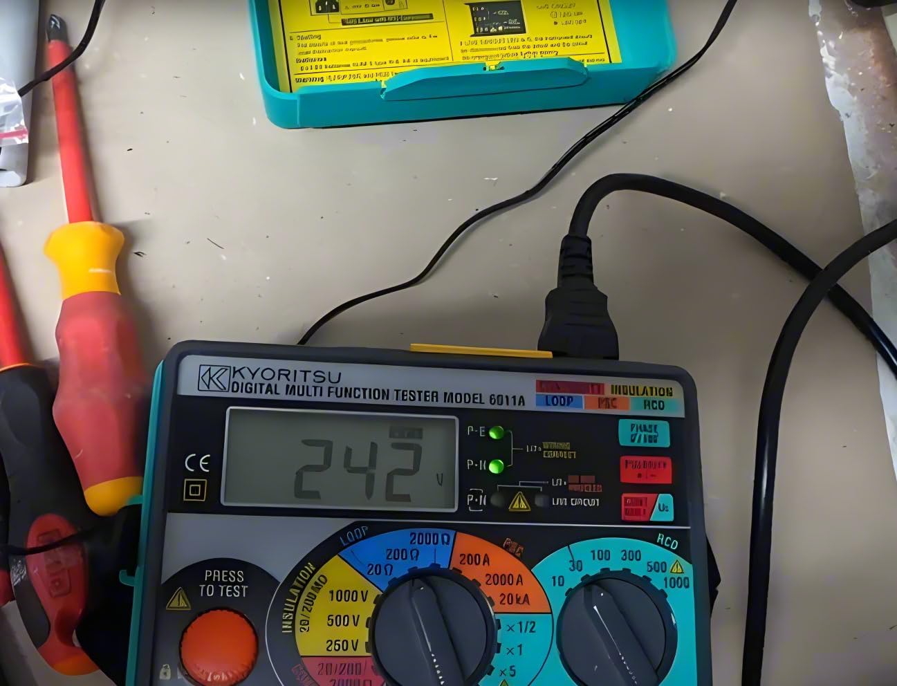
Figure 1: The KYORITSU KEW 6011A Multi-Function Tester. This image shows the front panel of the device with its display, rotary switches, and test buttons, indicating its compact and ergonomic design.
2. Safety Information
WARNING: Always read and understand all safety warnings and instructions before operating this instrument. Failure to do so may result in serious injury or death.
- This instrument complies with IEC 61010-1 CAT III 300V Pollution Degree 2, IEC 61010-2-034, and IEC 61557. Always adhere to these standards during use.
- Do not use the instrument if it appears damaged or if the test leads are compromised.
- Ensure the correct function and range are selected before making any measurements.
- Avoid contact with live circuits. Always assume circuits are live until proven otherwise.
- Wear appropriate personal protective equipment (PPE), including safety glasses and insulated gloves, when working with electrical systems.
- Do not operate the instrument in wet conditions or explosive atmospheres. The device is designed to IP54 rating, offering protection against dust and splashing water, but is not waterproof.
- Refer to the "Safety Warnings" section in the original instruction manual for complete safety guidelines.

Figure 2: Overview of KYORITSU Multi-Function Testers including KEW 6011A. This image provides a comparative table of specifications for various KYORITSU models, highlighting the features and capabilities of each, including safety standards compliance.
3. Key Features
The KEW 6011A is equipped with a comprehensive set of features for efficient and accurate electrical testing:
- 6-in-1 Functionality: Combines Continuity, Insulation, Loop, RCD, PSC Testing, and Contact Voltage Reading.
- Compliance: Fully complies with IEC 61557 standards.
- Robust Design: Designed to IP54 rating for protection against dust and splashing water.
- Live Circuit Check: Features LEDs for live circuit and wiring connection checks.
- Insulation Tests: Triple ranges at 250V, 500V, and 1000V.
- Loop & PSC Tests: Triple range loop and PSC tests with 15mA test current (200Ω/2000Ω range, No RCD Trip).
- RCD Testing: Phase angle selection on RCD ranges, capable of testing Standard, Selective, AC, and A (DC sensitive) type RCDs.
- Continuity Tests: Polarity switch and auto-null facility for accurate continuity measurements.
- Earth Probe: Includes an external earth probe for loop impedance testing on extraneous metalwork.
4. Setup and Initial Operation
4.1. Unpacking and Inspection
Carefully unpack the KEW 6011A and all accessories. Inspect for any signs of damage during transit. If any damage is found, contact your supplier immediately.
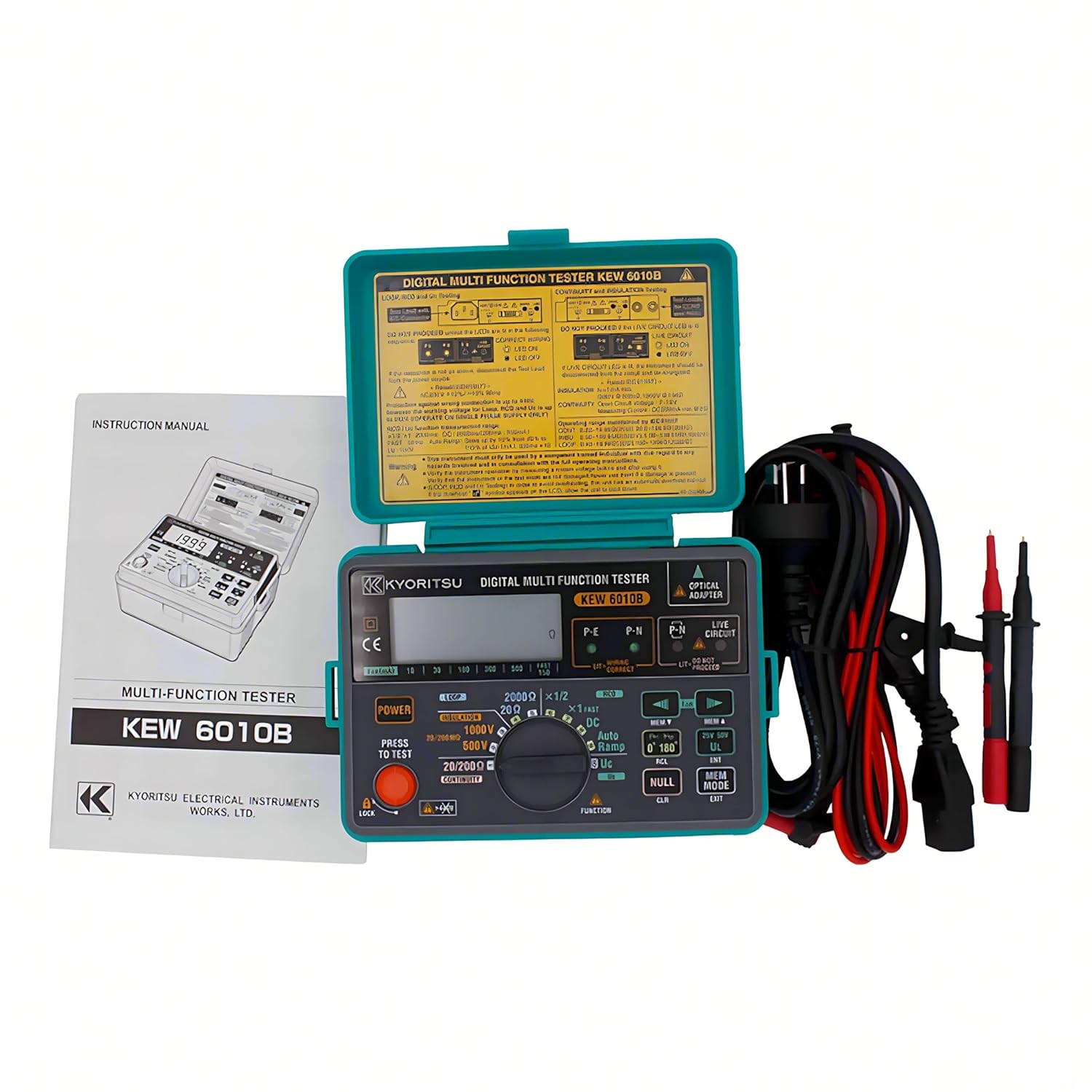
Figure 3: The KEW 6011A tester with its included accessories and instruction manual. This image displays the device alongside its test leads, carrying case, and the user manual, indicating a complete package.
4.2. Battery Installation
The KEW 6011A requires 8 x R6/LR6 (AA) batteries for operation. To install:
- Locate the battery compartment cover on the rear of the instrument.
- Use a screwdriver to loosen the screw(s) securing the cover.
- Insert 8 AA batteries, ensuring correct polarity as indicated inside the compartment.
- Replace the cover and tighten the screw(s).
4.3. Connecting Test Leads
Connect the appropriate test leads (e.g., 7122B Test leads, KAPM10 Molded plug test leads) to the input terminals of the KEW 6011A. Ensure connections are secure and free from damage.
5. Operating Instructions
This section outlines the procedures for performing various tests with the KEW 6011A.
5.1. Continuity Testing
Used to verify the continuity of protective conductors and equipotential bonding.
- Ensure the circuit under test is de-energized.
- Select the "Continuity" function on the rotary switch.
- Connect the test leads to the points to be measured.
- Press the "PRESS TO TEST" button. The resistance value will be displayed.
- Utilize the polarity switch and auto-null facility for precise measurements.
5.2. Insulation Resistance Testing
Measures the insulation resistance between conductors or between conductors and earth.
- Ensure the circuit under test is de-energized and isolated.
- Select the desired insulation test voltage (250V, 500V, or 1000V) on the rotary switch.
- Connect the test leads to the points where insulation resistance is to be measured.
- Press and hold the "PRESS TO TEST" button. The insulation resistance value will be displayed.
- Observe the "LIVE CIRCUIT" LED; do not proceed if it illuminates.
5.3. Loop Impedance Testing
Measures the impedance of the fault loop to ensure protective devices operate correctly.
- Ensure the circuit is live and at the rated voltage (230V AC, 50Hz).
- Select the "LOOP" function and the appropriate range (e.g., 200Ω/2000Ω).
- Connect the test leads to the live, neutral, and earth terminals of the circuit or socket.
- Press the "PRESS TO TEST" button. The loop impedance value will be displayed.
- Use the external earth probe (7132A) for testing on extraneous metalwork if required.
5.4. RCD (Residual Current Device) Testing
Verifies the correct operation and trip time of RCDs.
- Ensure the circuit is live and at the rated voltage (230V AC, 50Hz).
- Select the "RCD" function.
- Set the desired trip current (e.g., 10mA, 30mA, 100mA, 300mA, 500mA, 1000mA) and multiplier (x1/2, x1, x5).
- Connect the test leads to the live, neutral, and earth terminals of the circuit protected by the RCD.
- Press the "PRESS TO TEST" button. The RCD should trip, and the trip time will be displayed.
- Test various RCD types: Standard, Selective, AC, and A (DC sensitive breakers).
- Utilize the phase angle selection for comprehensive testing.
5.5. PSC (Prospective Short Circuit Current) Testing
Measures the prospective short circuit current at the point of test.
- Ensure the circuit is live and at the rated voltage (230V AC, 50Hz).
- Select the "PSC" function and the appropriate range (e.g., 200A, 2000A, 20kA).
- Connect the test leads to the live and neutral terminals of the circuit.
- Press the "PRESS TO TEST" button. The PSC value will be displayed.
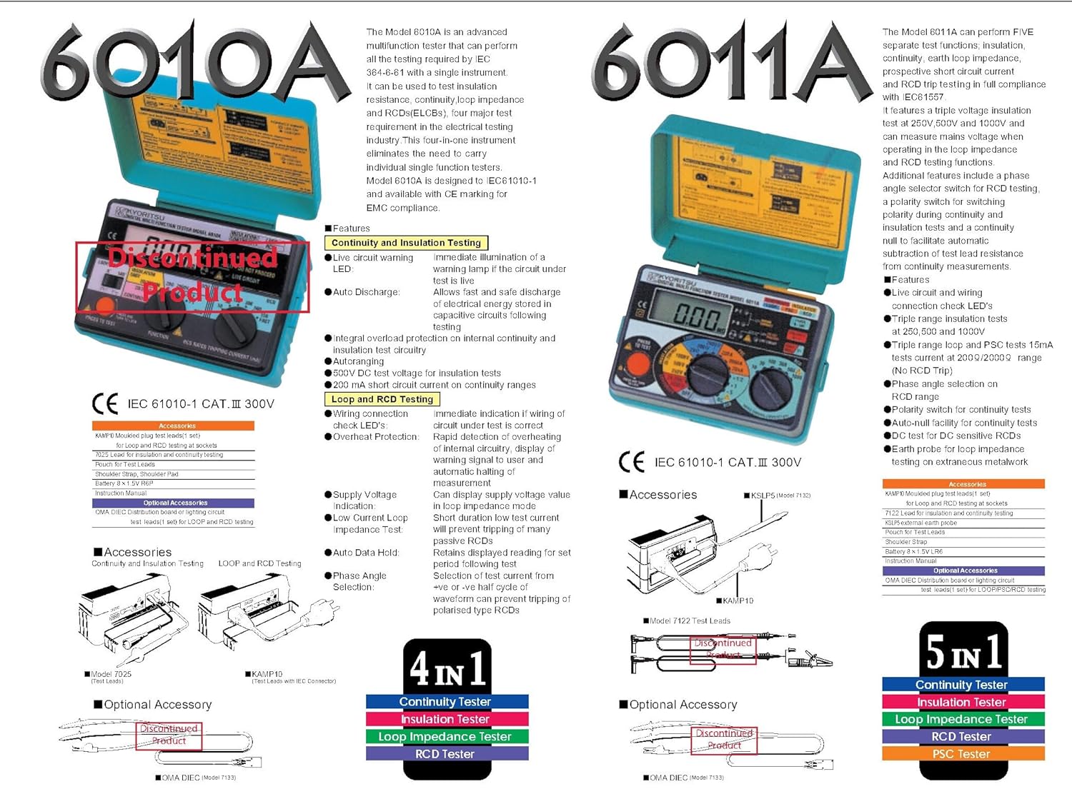
Figure 4: Detailed diagram illustrating the features and accessories of the KYORITSU KEW 6011A. This image provides a visual breakdown of the tester's capabilities, including its 5-in-1 functionality and compatible accessories like test leads and probes.
6. Maintenance
6.1. Cleaning
Wipe the instrument's casing with a soft, damp cloth. Do not use abrasive cleaners or solvents. Ensure the instrument is dry before storage or next use.
6.2. Battery Replacement
When the low battery indicator appears on the display, replace all 8 AA batteries promptly to ensure accurate measurements. Refer to Section 4.2 for battery installation instructions.
6.3. Fuse Replacement
The KEW 6011A uses a 0.5A/600V fuse (part number 8923). If the instrument fails to power on or a specific function is not working, the fuse may need replacement. Refer to the full instruction manual for detailed fuse replacement procedures.
6.4. Calibration
For continued accuracy and compliance, it is recommended to have the KEW 6011A calibrated by an authorized service center periodically, typically annually.
7. Troubleshooting
| Problem | Possible Cause | Solution |
|---|---|---|
| Instrument does not power on. | Dead or incorrectly installed batteries. Blown fuse. | Replace batteries (Section 6.2). Check and replace fuse (Section 6.3). |
| Inaccurate readings. | Low battery. Incorrect function/range selected. Dirty test leads/connections. Instrument needs calibration. | Replace batteries. Verify function and range. Clean test leads. Arrange for calibration. |
| RCD does not trip during test. | Incorrect RCD settings. Faulty RCD. Circuit not live. | Verify RCD current and multiplier settings. Check RCD functionality independently. Ensure circuit is live. |
| "LIVE CIRCUIT" LED illuminates during insulation test. | Circuit under test is energized. | Immediately disconnect. Ensure circuit is fully de-energized and isolated before proceeding. |
If the problem persists after attempting these solutions, contact KYORITSU customer support or an authorized service center.
8. Technical Specifications
| Parameter | Specification |
|---|---|
| Model | KEW 6011A (EC-KEW-6011A) |
| Rated Voltage | 230V AC +10%-15% [50Hz] |
| Insulation Test Voltages | 250V, 500V, 1000V |
| Loop/PSC Test Current | 15mA (200Ω/2000Ω range), 25A (2000A/20kA range) |
| PSC Ranges | 200A, 2000A, 20kA |
| RCD Trip Current Settings | 10, 30, 100, 300, 500, 1000mA (x1/2, x1); 10, 30, 100, 300mA (x5) |
| RCD Trip Time Duration | RCD x1/2, x1: 2000ms; RCD fast: 50ms |
| Safety Standard | IEC 61010-1 CAT III 300V Pollution Degree 2, IEC 61010-2-034, IEC 61557 |
| Ingress Protection (IP) Rating | IP54 |
| Power Source | 8 x R6/LR6 (AA) batteries |
| Dimensions (L x W x D) | 130mm x 183mm x 100mm |
| Weight | Approx. 1100g |
| Included Accessories | KAPM10 (Molded plug test leads), 7122B (Test leads), 7132A (External earth probe), 8923 (Fuse 0.5A/600V), 9092 (Cord case), 9121 (Shoulder Strap), R6(AA) x 8 batteries, Instruction Manual |
| Optional Accessories | 7133B (Distribution board test leads) |
9. Warranty and Support
9.1. Warranty Information
The KYORITSU KEW 6011A comes with a manufacturer's warranty. Please refer to the warranty card included with your product or visit the official KYORITSU website for detailed warranty terms and conditions. Spare parts availability is typically 1 year.
9.2. Customer Support
For technical assistance, service, or inquiries regarding your KEW 6011A, please contact KYORITSU customer support. Contact information can typically be found in the full instruction manual or on the official KYORITSU website.
KYORITSU ELECTRICAL INSTRUMENTS WORKS, LTD.
http://www.kew.co.jp
Ask a question about this manual
Ask about setup, troubleshooting, compatibility, parts, safety, or missing instructions. Manuals+ will review the question and use this page’s manual context to help answer it.