
1. Introduction
This instruction manual provides essential information for the safe and effective installation, operation, and maintenance of the Heschen CT1-25M/40 Modular AC Contactor. Please read this manual thoroughly before installation and operation to ensure proper functionality and to prevent potential hazards. Keep this manual for future reference.
2. Safety Information
Warning: Electrical installation and maintenance should only be performed by qualified and authorized personnel. Failure to comply with safety instructions may result in electric shock, fire, or serious injury.
- Always disconnect power to the circuit before installing, wiring, or performing any maintenance on the contactor.
- Ensure that the supply voltage and current ratings match the specifications of the CT1-25M/40 contactor.
- Use appropriate personal protective equipment (PPE) during installation and maintenance.
- Verify all connections are secure and correctly wired according to the provided diagrams and local electrical codes.
- Do not operate the contactor if it is damaged or appears to be malfunctioning.
3. Product Overview
The Heschen CT1-25M/40 is a modular AC contactor designed for switching AC loads in domestic and industrial applications. It features a 4-pole configuration with four normally open (4NO) contacts, a 220V AC coil, and a manual control switch for local operation. The contactor is designed for 35mm DIN rail mounting, ensuring easy integration into standard electrical enclosures.
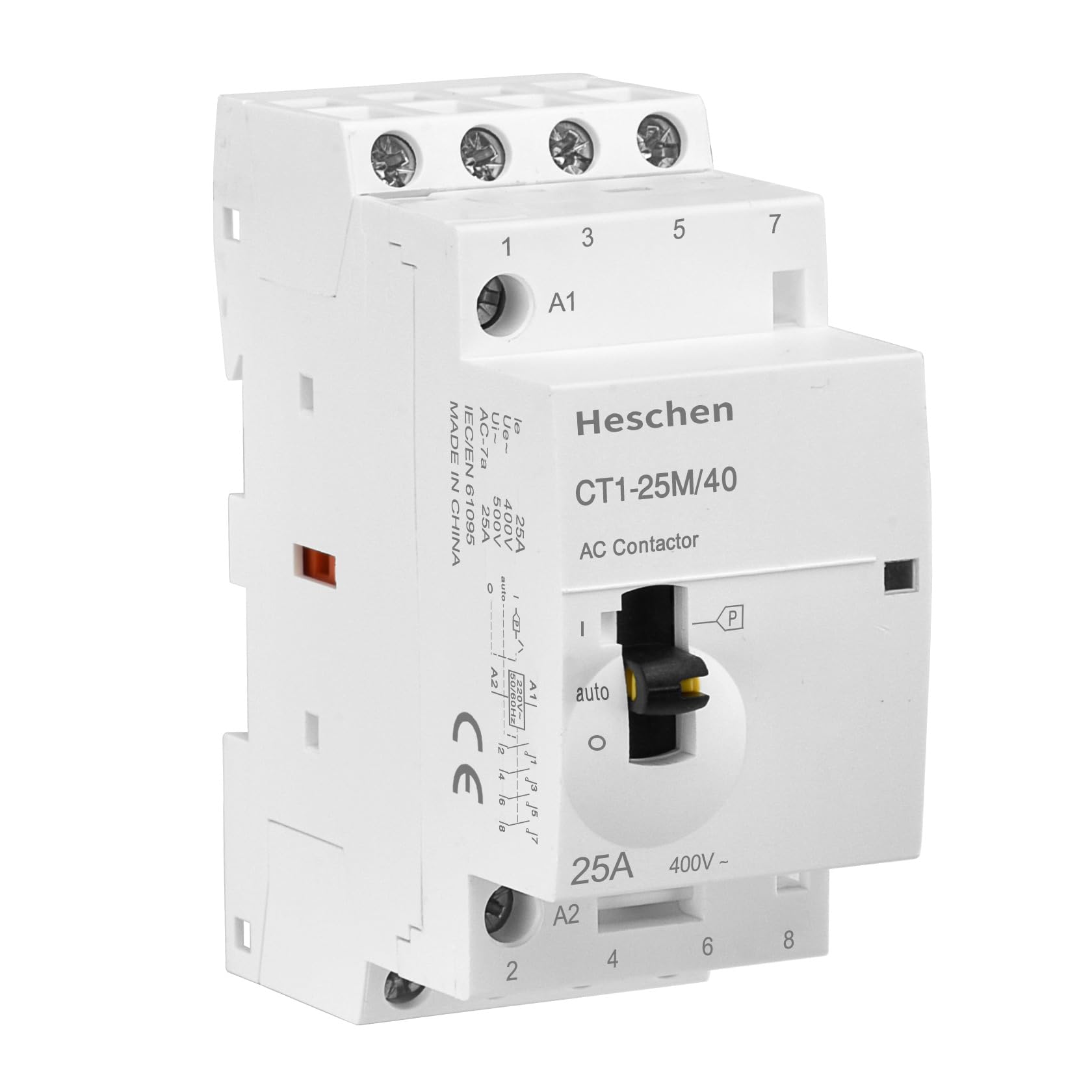
Figure 3.1: Front-side view of the Heschen CT1-25M/40 Modular AC Contactor, showing terminals and manual control switch.
Key Features:
- Rated Current: 25A
- Poles: 4 (4 Normally Open contacts)
- Coil Voltage: 220V AC
- Mounting: 35mm DIN Rail
- Integrated Manual Control Switch
- CE Compliant
4. Specifications
The following table details the technical specifications for the Heschen CT1-25M/40 Modular AC Contactor:
| Parameter | Value |
|---|---|
| Model Number | CT1-25M/40 |
| Rated Current (In) | 25A |
| Rated Operating Voltage (Ue) | 400V |
| Rated Insulation Voltage (Ui) | 500V |
| Coil Voltage (Us) | 220V AC |
| Contact Configuration | 4 Normally Open (4NO) |
| Poles | 4P |
| Standard | IEC/EN 61095 |
| Mounting Type | 35mm DIN Rail |
| AC-7a Rating | 25A |
| Package Dimensions | 9 x 8 x 4 cm |
| Weight | 225 grams |
| Country of Origin | China |

Figure 4.1: Product dimensions of the Heschen CT1-25M/40 AC Contactor.

Figure 4.2: Detailed technical specifications including wiring ability and fastening torque.
5. Setup and Installation
Before proceeding with installation, ensure all power is disconnected from the circuit. This contactor is designed for mounting on a standard 35mm DIN rail.
5.1. Mounting
- Locate a suitable position on a 35mm DIN rail within your electrical enclosure.
- Align the contactor's DIN rail clips with the rail.
- Press the contactor firmly onto the DIN rail until it clicks securely into place. Ensure it is stable and does not wobble.

Figure 5.1: Bottom view illustrating the DIN rail mounting mechanism.
5.2. Wiring
Refer to the wiring diagram below for correct connections. Ensure all wires are of appropriate gauge for the rated current and are securely terminated to prevent loose connections and overheating.
- Coil Connections (A1, A2): Connect the 220V AC control voltage to terminals A1 and A2. A1 is typically the phase (L) and A2 is the neutral (N).
- Main Circuit Connections (1, 3, 5, 7 and 2, 4, 6, 8): Connect the incoming power supply to terminals 1, 3, 5, and 7. Connect the load to terminals 2, 4, 6, and 8. These are the four normally open power contacts.
- Grounding: Ensure proper grounding of the electrical enclosure and associated equipment.

Figure 5.2: Typical wiring diagram for the CT1-25M/40 AC Contactor with control equipment.
After wiring, double-check all connections for correctness and tightness. Apply a fastening torque of 0.8 N·m for both main circuit and control circuit terminals.
6. Operating Instructions
The Heschen CT1-25M/40 contactor can be operated in automatic mode via its coil or manually using the integrated control switch.
6.1. Manual Control Switch
The contactor features a manual control switch on its front face. This switch has three positions:
- 'O' (Off): In this position, the main contacts are open, and the load is disconnected, regardless of the coil's state.
- 'I' (On): In this position, the main contacts are closed, and the load is connected, regardless of the coil's state.
- 'Auto': In this position, the contactor operates automatically based on the control signal applied to the A1 and A2 coil terminals. When the coil is energized (220V AC applied), the main contacts close. When the coil is de-energized, the main contacts open.
Use the manual control switch for testing, maintenance, or temporary override of automatic control. Always return the switch to the 'Auto' position for normal operation.

Figure 6.1: Top view highlighting the manual control switch and electrical ratings.
7. Maintenance
Regular inspection and maintenance can extend the lifespan of your Heschen CT1-25M/40 AC Contactor. Always disconnect power before performing any maintenance.
- Visual Inspection: Periodically check the contactor for any signs of physical damage, discoloration, or loose connections.
- Terminal Tightness: Ensure all terminal screws remain tight. Re-tighten if necessary, adhering to the specified torque of 0.8 N·m.
- Cleaning: Keep the contactor free from dust and debris. Use a dry, soft cloth for cleaning. Do not use liquid cleaners or solvents.
- Contact Wear: While internal contacts are not user-serviceable, excessive arcing or contact welding may indicate the need for replacement.
There are no user-serviceable parts inside the contactor. If the device malfunctions, it should be replaced by a qualified technician.
8. Troubleshooting
This section provides solutions to common issues encountered with the CT1-25M/40 AC Contactor.
| Problem | Possible Cause | Solution |
|---|---|---|
| Contactor does not energize in 'Auto' mode | No control voltage to A1/A2; Incorrect wiring; Faulty coil | Check control circuit voltage; Verify A1/A2 wiring; Test coil continuity (with power off) |
| Contactor hums loudly | Loose connections; Incorrect voltage; Mechanical issue | Tighten terminals; Verify coil voltage; Inspect for foreign objects (with power off) |
| Contactor contacts remain open/closed | Manual switch in 'O' or 'I' position; Welded contacts; Mechanical fault | Set manual switch to 'Auto'; Replace contactor if contacts are welded or mechanism is faulty |
| Overheating | Overload; Loose connections; Poor ventilation | Reduce load or use higher rated contactor; Tighten all connections; Ensure adequate airflow in enclosure |
If troubleshooting steps do not resolve the issue, contact a qualified electrician or Heschen customer support.
9. Warranty and Support
For warranty information and technical support, please refer to your purchase documentation or contact your Heschen product supplier. Ensure you have your product model number (CT1-25M/40) and purchase date available when seeking support.