1. Product Overview
The DALY BMS 250A 8S-24S is an intelligent Battery Management System designed for 24V to 72V LiFePO4, Li-ion, and LTO battery packs. It features built-in Bluetooth connectivity and 1A continuous active cell balancing with a peak current up to 1.2A, ensuring optimal battery performance and longevity. This BMS provides comprehensive protection and supports various communication protocols for versatile applications.
- Enhanced Battery Safety: Offers protection against overcharging, over-discharging, overcurrent, short circuits, and extreme temperatures.
- Extra Protection Features: Includes pre-charge protection, wrong connection or missing connection of wires, parallel connection current limiting, and cell balancing.
- Battery Management System: Manage your battery easily with Android or iOS mobile app via Bluetooth connectivity. Monitor status, adjust settings, and control charge/discharge.
- Voltage Compatibility: Compatible with 8S, 10S, 12S, 13S, 14S, 15S, 16S, 17S, 20S, 21S, 22S, 24S configurations (24V, 36V, 48V, 60V, 72V battery packs).
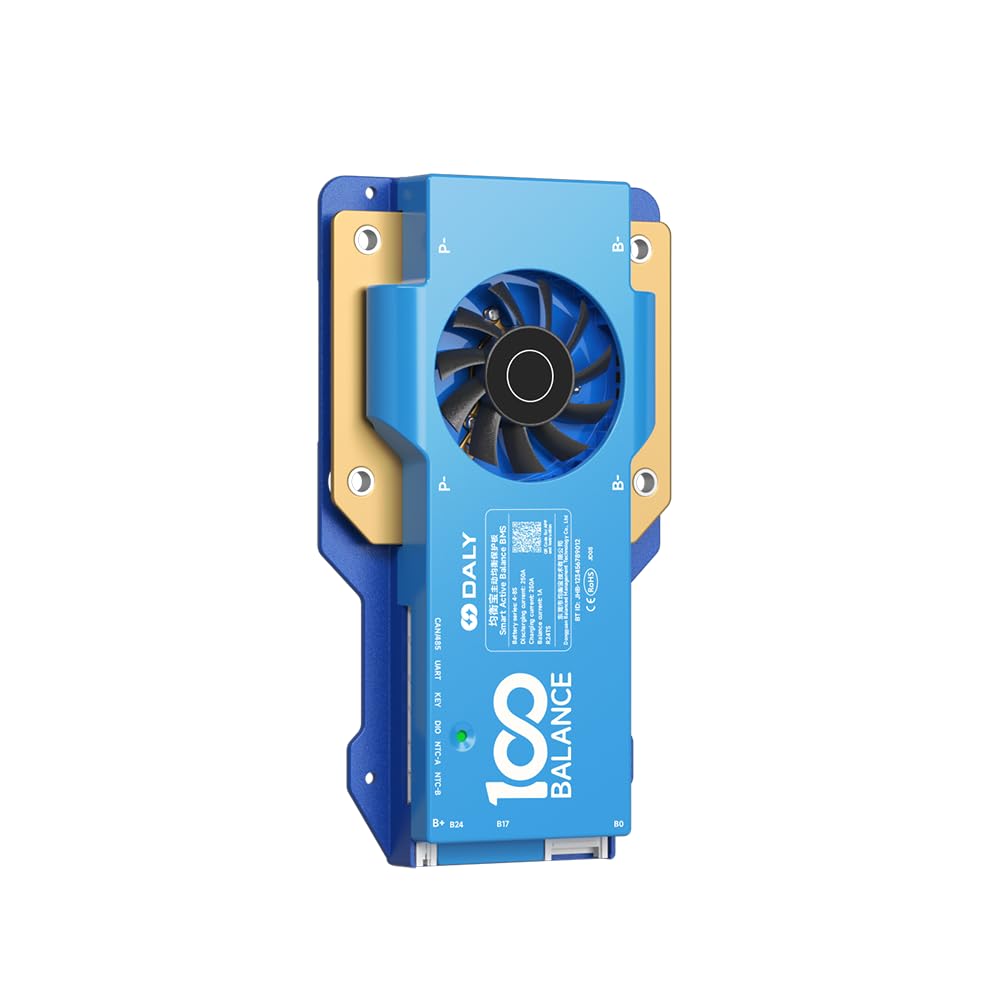
Figure 1: DALY BMS 250A 8S-24S Smart Active Balance Battery Management System.
Video 1: Introduction to the 100BALANCE Smart Active Balance BMS, highlighting its features and balancing capabilities.
2. Product Specifications
Key technical specifications for the DALY BMS 250A 8S-24S model.
| Specification | Value |
|---|---|
| Brand | 100 BALANCE |
| Model Number | 250A CAN |
| Compatible Strings | 8S - 24S |
| Continuous Discharge Current | 250A |
| Max Discharge Current | 375A (delay time: 1±0.8s) |
| Continuous Charge Current | 250A |
| Active Cell Balancing Current | 1A |
| Communication Interfaces | Bluetooth, RS485, CAN |
| Dimensions (approx.) | 195mm (L) x 109mm (W) x 26mm (H) |
| Weight (approx.) | 660g |
| Color | Blue |

Figure 2: Detailed product specifications including dimensions and cell compatibility.
3. Setup and Wiring Installation
Proper wiring is crucial for the safe and effective operation of your BMS. Always ensure correct polarity and sequence during installation.
3.1 Wiring Sequence
- Connect the black wire of the sampling cable to the total negative terminal (B-) of the battery pack.
- Connect the red wires of the sampling cable to the positive terminals of each cell in sequence, starting from the first cell's positive terminal (B1+), then B2+, and so on, up to the last cell's positive terminal (B+).
- Ensure all wires are securely soldered or connected. Seal any unused wires with insulation tape.
- Measure the voltage of each wire in the sampling harness using a multimeter to confirm correct voltage readings and consistency before plugging into the BMS.
- Plug the NTC (temperature sensor) cable into the NTC-A port on the BMS.
- Connect the main B- cable from the battery pack to the B- terminal on the BMS.
- Insert the sampling wire harness into the designated port on the BMS.
- Connect the main P- cable from the BMS to the load/charger negative terminal.
Important: Follow the wiring sequence strictly. Incorrect wiring can damage the BMS and battery pack. Miswiring protection is limited to 6 strings; connecting more than 6 strings incorrectly will damage your BMS.

Figure 3: Exploded view illustrating the internal components and cooling design of the DALY BMS.
Video 2: Detailed guide on the introduction and wiring installation of the 100BALANCE Smart Active Balance BMS.
4. Operation and Communication
The DALY BMS offers multiple ways to monitor and control your battery system.
4.1 Mobile App (Bluetooth)
Connect to the BMS via Bluetooth using the dedicated Android or iOS mobile app. The app allows you to:
- Monitor real-time battery status (voltage, current, temperature, SOC).
- Adjust various protection parameters.
- Control charge and discharge functions.
4.2 PC Software
For advanced monitoring and configuration, connect the BMS to a PC using a UART, RS485, or CAN communication module. The PC software provides a comprehensive interface for:
- Detailed data logging and analysis.
- Parameter customization and firmware upgrades.
- Monitoring multiple BMS units (if applicable).
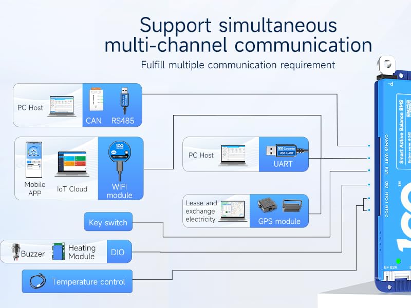
Figure 4: Diagram illustrating various communication methods for the DALY BMS, including PC Host, Mobile APP, and IoT Cloud.
Video 3: Tutorial on how to connect the 100BALANCE Smart BMS to the PC host software for monitoring and configuration.
5. Accessories
The DALY BMS supports various accessories to extend its functionality and provide additional monitoring options.
- UART Cable: For PC connection (PC Host software).
- RS485 Cable: For communication with compatible devices and PC.
- CAN Bus Module: For CAN communication with inverters and other systems.
- WiFi Module: Enables remote monitoring and control via IoT Cloud.
- LCD Displays (3.0 inch, 4.3 inch Touch Display): For real-time battery information display and parameter adjustment without a PC or phone.
- Heating Module: Used in cold environments to activate the BMS and ensure optimal battery temperature.
- Key Switch Button: Can be used to switch the discharge MOSFET on/off.
- NTC Cable: Additional temperature sensors.
- Inverter Connection Line: For direct connection to compatible inverters.
- Buzzer: For audible alerts.
- Parallel Interface Board / Parallel Module: For safe parallel connection of multiple battery packs.

Figure 5: Overview of various accessories compatible with the DALY Smart Active Balance BMS.
6. Parallel Connection Precautions
When connecting multiple lithium battery packs in parallel, it is essential to follow specific precautions to ensure safety and proper operation.
- Voltage Matching: Ensure that the voltage of each battery pack is within 1V of each other before connecting them in parallel. This prevents high current surges between packs.
- Discharge MOS Disconnection: Before paralleling battery packs, manually disconnect the discharging MOSFET using the Bluetooth APP or PC software. This prevents accidental short circuits or damage during connection.
- Parallel Module: Utilize a parallel module or interface board if available, as it helps manage current distribution and ensures safe paralleling.
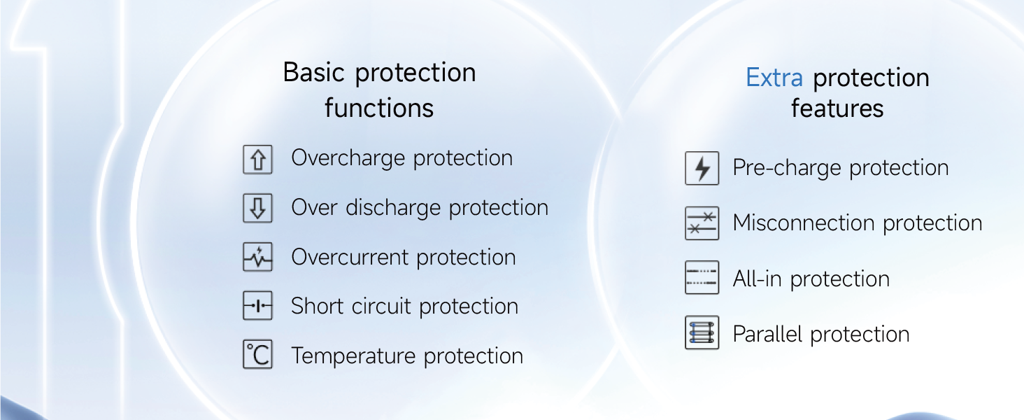
Figure 6: Diagram illustrating the basic and extra protection functions of the DALY BMS, including parallel protection.
7. Troubleshooting
For any operational issues or alarms, refer to the mobile app or PC software for real-time status and historical fault data. The BMS provides detailed alarm information to help diagnose and resolve problems.
- Alarm List: Check the 'Alarm List' section in the PC software or mobile app for active and historical fault records.
- Parameter Settings: Verify that all parameters (e.g., cell voltage limits, current limits, temperature limits) are correctly configured for your specific battery type and application.
- Wiring Check: Re-verify all wiring connections, especially the sampling cables, for proper sequence and secure contact.
8. Warranty and Support
The DALY BMS 250A 8S-24S comes with a 3-year warranty from the date of purchase. This warranty covers manufacturing defects and ensures reliable operation under normal use conditions.
For technical support, troubleshooting assistance, or warranty claims, please contact the manufacturer or your authorized dealer. Ensure you have your product model number and purchase details available when seeking support.
Manufacturer: Dongguan Balanced Management Technology Co., Ltd