1. Introduction
This manual provides essential information for the proper installation, operation, and maintenance of your SURRYN SDS3MS 3-Axis Digital Readout (DRO) Display Set. This system is designed to enhance precision and efficiency in various machining applications, including lathes and milling machines. Please read this manual thoroughly before using the product to ensure safe and optimal performance.
2. Product Overview
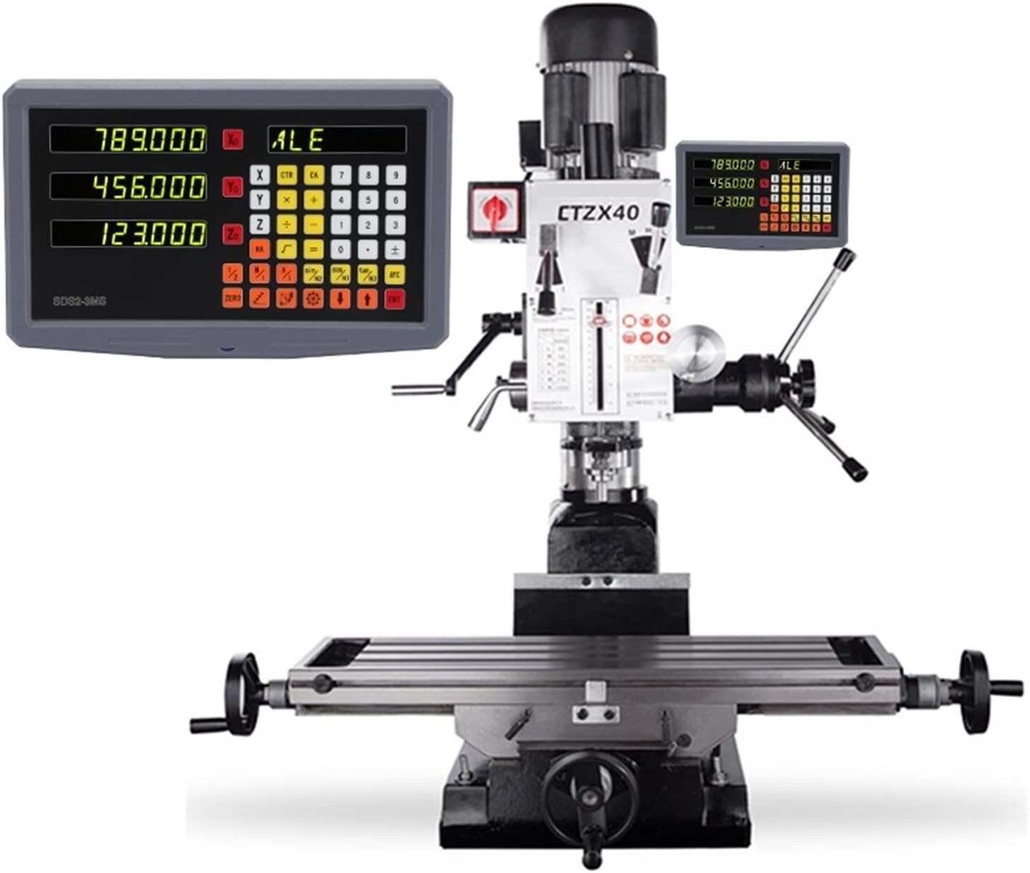
The SURRYN SDS3MS Digital Readout Display Set is a high-precision measurement system for machine tools. It includes a 3-axis DRO display unit and three KA300 series glass linear scales (rulers) with encoder sensors, ranging from 120mm to 1020mm in travel length. The system is engineered for stable performance and user-friendly operation.
2.1 Package Contents
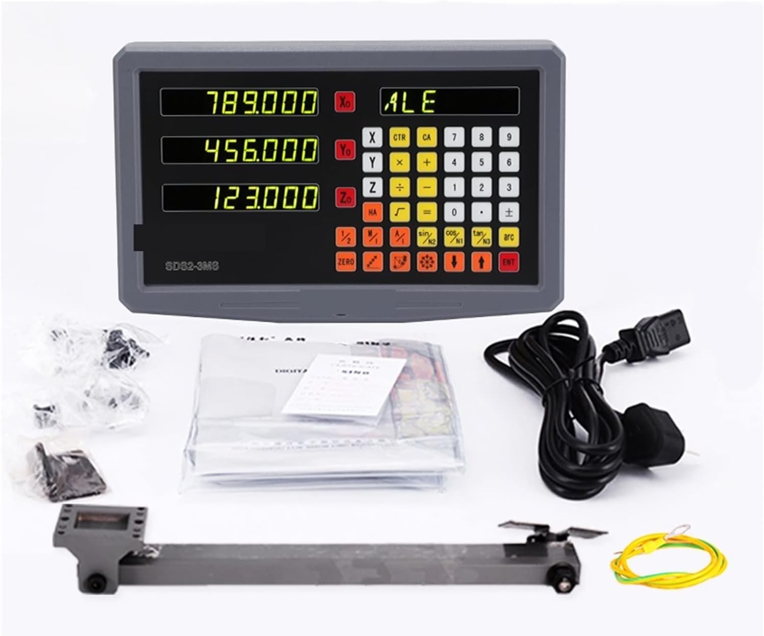
The complete package typically includes:
- One (1) SDS3MS 3-Axis Digital Readout Display Unit
- Three (3) KA300 Series Glass Linear Scales (various lengths)
- Mounting brackets and hardware for scales and display
- Power cable
- User Manual (this document)

2.2 Key Features
- Professional Design: Features a robust die-casting alloy shell with electric pensu processing for dustproof and wear-resistant properties, ensuring good shielding.
- High Stability: Independent power supply design contributes to high stability and strong anti-jamming capabilities.
- Enhanced Performance: Utilizes a low-power consumption, high-sampling rate, and high-precision chip for powerful data processing and improved program stability.
- User-Friendly Interface: Humanized design with a 7-level brightness adjustment function for display, square-shaped ergonomic buttons for comfortable and efficient operation.
- Advanced Functions: Supports mm/inch conversion, absolute/relative conversion, and direct functional operations such as sine, cosine, and tangent.
3. Setup and Installation
Proper installation is crucial for the accuracy and longevity of your DRO system. It is recommended that installation be performed by individuals familiar with machine tool setup.
3.1 Unpacking and Inspection
- Carefully unpack all components and verify against the package contents list.
- Inspect all items for any signs of shipping damage. Report any damage to your supplier immediately.
3.2 Mounting the Linear Scales
The linear scales (KA300 series rulers) must be mounted parallel to the machine's axis of travel. Ensure the mounting surface is clean and flat.
- Select the appropriate scale length for each axis (X, Y, Z).
- Attach the scale body securely to the stationary part of the machine using the provided brackets and hardware.
- Mount the reading head to the moving part of the machine, ensuring it moves freely along the scale without binding.
- Maintain a small, consistent gap between the reading head and the scale body as specified in the detailed installation guide (refer to the included manual for precise measurements).

3.3 Mounting the DRO Display Unit
- Choose a location for the display unit that is easily visible and accessible to the operator, away from excessive vibration or heat.
- Use the provided mounting arm and brackets to secure the display unit. The watch box, made of ABS high-strength material, allows for adjustment of the tilt angle for optimal viewing.
3.4 Electrical Connections
- Connect each linear scale's cable to the corresponding axis input port on the back of the DRO display unit (X, Y, Z). Ensure connections are firm.
- Plug the power cable into the display unit and then into a suitable power outlet (50 Hz ~ 60 Hz).
- Verify all connections before powering on the unit.
4. Operating Instructions
The SDS3MS DRO unit offers a range of functions to assist with precise machining operations.
4.1 Basic Functions
- Power On/Off: Press the power button to turn the unit on or off.
- Zero Setting: Press the 'ZERO' button for the desired axis (X, Y, or Z) to set the current position to zero.
- mm/inch Conversion: Use the dedicated 'mm/inch' button to switch between metric and imperial units.
- Absolute/Relative Conversion: Toggle between absolute (ABS) and incremental (INC) measurement modes using the 'ABS/INC' button.
- Brightness Adjustment: The display features a 7-level brightness adjustment. Refer to the detailed manual for specific button combinations to adjust brightness according to your environment.
4.2 Advanced Functions
The SDS3MS supports various advanced functions for complex machining tasks:
- 200-Point Auxiliary Z: This function assists with specific Z-axis operations.
- Trigonometric Functions: Direct access to sine, cosine, and tangent functions for calculations.
- Hole Pattern Calculations: Features for calculating bolt circle patterns and linear hole patterns.
- Tool Compensation: Functions for tool radius and length compensation.
For detailed instructions on advanced functions, please consult the comprehensive user manual included with your product.
5. Maintenance
Regular maintenance ensures the accuracy and extends the lifespan of your DRO system.
- Cleaning: Keep the display unit and linear scales clean. Use a soft, dry cloth to wipe surfaces. Avoid abrasive cleaners or solvents.
- Scale Protection: Ensure the linear scales are protected from chips, coolant, and dust. Regularly check the integrity of the scale covers.
- Cable Inspection: Periodically inspect all cables for wear, cuts, or damage. Replace damaged cables immediately to prevent electrical hazards or signal loss.
- Environmental Conditions: Operate the DRO system within its specified environmental conditions (temperature, humidity) to prevent damage.
6. Troubleshooting
This section addresses common issues you might encounter with your DRO system.
6.1 Display Not Powering On
- Check Power Connection: Ensure the power cable is securely plugged into the display unit and a live power outlet.
- Power Source: Verify the power outlet is functional by plugging in another device.
- Fuse: Check if the internal fuse (if accessible) has blown. Consult a qualified technician for fuse replacement.
6.2 Inaccurate Readings or Jumps
- Scale Alignment: Ensure the linear scales are perfectly parallel to the machine's travel axis and the reading head is properly aligned.
- Cleanliness: Clean the surface of the glass scales and the reading head. Dust, oil, or debris can interfere with accurate readings.
- Cable Connection: Verify that the encoder cables are securely connected to both the scales and the display unit.
- Vibration: Excessive machine vibration can affect readings. Ensure the DRO display and scales are mounted securely.
6.3 Buttons Unresponsive
- Power Cycle: Turn off the DRO unit, wait a few seconds, and then turn it back on.
- Physical Obstruction: Check for any physical debris or damage preventing button presses.
If you encounter issues not covered here, or if troubleshooting steps do not resolve the problem, please contact SURRYN customer support.
7. Specifications
Detailed technical specifications for the SURRYN SDS3MS Digital Readout Display Set.
| Feature | Specification |
|---|---|
| Manufacturer | SURRYN |
| Model Number | 1005003773324178 |
| Part Number | 1005003773324178 |
| Display Type | SDS3MS Digital Readout |
| Coordinate Number | Three coordinates (3-axis) |
| Input Signal | TTL |
| Allowable Input Signal Frequency | >100 KHz |
| Resolution Options | 0.1 microns, 0.2 microns, 0.5 microns, 1 micron, 2 microns, 5 microns, 10 microns |
| Power Supply | 50 Hz ~ 60 Hz |
| Power Consumption | 25 VA |
| Linear Scales | KA300 series glass linear scales (3 PCS) |
| Scale Travel Lengths | 120mm ~ 1020mm (various options) |
| Item Weight | 0.353 ounces (Display unit only, approximate) |
| Package Dimensions | 1.18 x 0.79 x 0.39 inches (Display unit only, approximate) |
| Date First Available | June 18, 2024 |
7.1 KA-300 Series Dimensions
The following table provides general dimensions for the KA-300 series linear scales. Refer to the specific scale's documentation for exact measurements.

8. Warranty and Support
SURRYN products are manufactured to high-quality standards. For specific warranty information, please refer to the warranty card included with your product or contact SURRYN customer service directly.
8.1 Customer Support
If you have any questions regarding the installation, operation, or maintenance of your SURRYN SDS3MS Digital Readout Display Set, please contact SURRYN customer support through the official channels provided on the product packaging or website. Please have your model number (1005003773324178) and purchase details ready when contacting support.


