1. Introduction
This user manual provides comprehensive instructions for the AJSWISH SRD-24VDC-SL-C 2-Way 24V 10A 250VAC Relay Module. Please read this manual carefully before using the product to ensure proper operation and safety. This module is designed for various electronic control applications, offering reliable switching capabilities.
2. Product Overview
The SRD-24VDC-SL-C is a 2-channel relay module capable of handling 24V DC control signals and switching AC loads up to 250V at 10A, or DC loads up to 30V at 10A. It features two independent relays, each with Normally Open (NO), Common (COM), and Normally Closed (NC) contacts, providing flexibility for various circuit configurations. The module is designed for chassis mounting.
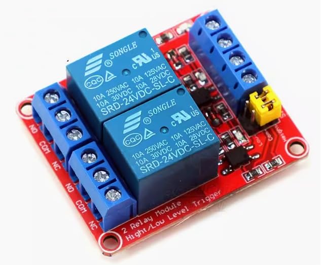
Figure 2.1: AJSWISH SRD-24VDC-SL-C 2-Way 24V 10A 250VAC Relay Module. This image shows the compact red PCB with two blue SRD-24VDC-SL-C relays, each connected to blue screw terminals for NO, COM, and NC contacts. A yellow jumper cap is visible on the input side, likely for high/low level trigger selection. The module is clearly labeled "2 Relay Module High/Low Level Trigger".
3. Features
- Dual Channel Operation: Equipped with two independent relays for controlling two separate circuits.
- High Current Capacity: Each relay can switch up to 10A at 250VAC or 10A at 30VDC.
- Versatile Control Voltage: Operates with a 24V DC control signal.
- Flexible Output Contacts: Each relay provides Normally Open (NO), Common (COM), and Normally Closed (NC) contacts.
- Chassis Mount Design: Suitable for secure installation within enclosures or systems.
- High/Low Level Trigger: Supports configurable trigger levels for input signals.
4. Specifications
| Parameter | Value |
|---|---|
| Model Number | SRD-24VDC-SL-C |
| Control Voltage | 24V DC |
| Max AC Load | 10A @ 250VAC |
| Max DC Load | 10A @ 30VDC |
| Contact Type | Normally Closed (NC), Normally Open (NO), Common (COM) |
| Contact Material | Aluminum |
| Mounting Type | Chassis Mount |
| Product Dimensions | 3.15 x 1.18 x 0.79 inches (80 x 30 x 20 mm) |
| Manufacturer | GZEduld-US |
5. Package Contents
- 1 x SRD-24VDC-SL-C 2-Way 24V 10A 250VAC Relay Module
- 1 x Piece of accessories (as specified by manufacturer)
6. Setup and Wiring
Before connecting the module, ensure all power sources are disconnected. Incorrect wiring can damage the module or connected devices.
6.1. Pinout Description
- VCC: Power supply for the module (24V DC).
- GND: Ground connection for the module.
- IN1, IN2: Control signal inputs for Relay 1 and Relay 2 respectively. These inputs trigger the relays based on the configured high/low level.
- NO (Normally Open): Contact that is open when the relay is de-energized and closes when energized.
- COM (Common): Common contact for the relay switch.
- NC (Normally Closed): Contact that is closed when the relay is de-energized and opens when energized.
6.2. Trigger Level Selection
The module supports both high-level and low-level trigger modes. This is typically configured via a jumper cap on the module (refer to Figure 2.1 for location).
- High-Level Trigger: The relay activates when the input signal (IN1/IN2) is high (e.g., 24V).
- Low-Level Trigger: The relay activates when the input signal (IN1/IN2) is low (e.g., 0V or GND).
6.3. Wiring Diagram (Conceptual)
Below is a conceptual wiring guide. Always refer to specific application requirements and safety standards.
- Connect VCC to a stable 24V DC power supply positive terminal.
- Connect GND to the negative terminal of the 24V DC power supply.
- Connect your control signal source to IN1 and IN2. Ensure the trigger level (high/low) is correctly set.
- For the load circuit:
- To switch a load ON when the relay is activated (Normally Open configuration): Connect one side of the load to the power source, and the other side of the load to the NO terminal. Connect the COM terminal to the return path of the power source.
- To switch a load OFF when the relay is activated (Normally Closed configuration): Connect one side of the load to the power source, and the other side of the load to the NC terminal. Connect the COM terminal to the return path of the power source.
Note: For AC loads, ensure proper insulation and safety precautions are taken. Consult a qualified electrician if unsure.
7. Operating Instructions
Once the module is correctly wired and powered, the relays can be controlled by applying the appropriate signal to the IN1 and IN2 pins.
- Relay Activation: When the control signal (IN1 or IN2) matches the configured trigger level (high or low), the corresponding relay will energize. You may hear a click sound, and an indicator LED (if present) on the module will illuminate.
- Contact State Change:
- When energized, the connection between COM and NO will close, and the connection between COM and NC will open.
- When de-energized, the connection between COM and NO will open, and the connection between COM and NC will close.
- Deactivation: When the control signal is removed or changed to the opposite level, the relay will de-energize, returning its contacts to their default state.
Ensure that the load current and voltage do not exceed the module's specified maximum ratings to prevent damage.
8. Maintenance
The SRD-24VDC-SL-C Relay Module is designed for reliable operation with minimal maintenance. Follow these guidelines to ensure longevity:
- Keep Clean: Periodically inspect the module for dust or debris accumulation. Use a soft, dry brush or compressed air to clean.
- Environmental Conditions: Operate the module within its specified temperature and humidity ranges. Avoid exposure to excessive moisture, corrosive gases, or extreme temperatures.
- Secure Connections: Ensure all wiring connections are secure and free from corrosion. Loose connections can lead to intermittent operation or overheating.
- Avoid Overloading: Do not exceed the maximum current and voltage ratings of the relays. Consistent overloading will significantly reduce the lifespan of the module.
9. Troubleshooting
If you encounter issues with your SRD-24VDC-SL-C Relay Module, consider the following common problems and solutions:
| Problem | Possible Cause | Solution |
|---|---|---|
| Relay does not activate. |
|
|
| Load does not switch ON/OFF. |
|
|
| Module gets excessively hot. |
|
|
If the problem persists after attempting these solutions, please contact customer support.
10. Warranty and Support
AJSWISH is committed to providing high-quality products and customer satisfaction. This product comes with a standard manufacturer's warranty against defects in materials and workmanship.
For technical assistance, troubleshooting, or warranty inquiries, please do not hesitate to contact our support team. We are available 24/7 to assist you. Please feel free to contact us via email.
Thank you for choosing AJSWISH.


