Latuwa H2510
Latuwa Trimmer Head Replacement Manual
Model: 841P035132S
Introduction
This manual provides detailed instructions for the installation and maintenance of the Latuwa Trimmer Head, replacement part number 841P035132S. This product is designed as a direct replacement for specific Hyper Tough gas string trimmer models, ensuring optimal performance and compatibility.
Compatibility
This replacement trimmer head (Part No. 841P035132S) is compatible with the following Hyper Tough gas string trimmer models:
- Hyper Tough H2500 Curved Shaft Gas String Trimmer
- Hyper Tough H2510 Curved Shaft Gas String Trimmer
- Hyper Tough H2520 Straight Shaft Gas String Trimmer
Package Contents
Please verify that all components listed below are present in your package:
- 1x String Trimmer Head
- 1x Adapter Nut
- 1x 5/16" -18 Right-Hand Thread Bump Knob (Red)
- 2x 5/16" -18 Left-Hand Thread Bump Knobs (Black)
- 1x Spring
- 1x Washer

Figure 1: Complete package contents of the Latuwa Trimmer Head replacement kit.
Setup and Installation
Before beginning installation, ensure your string trimmer is turned off and disconnected from any power source (e.g., spark plug wire removed for gas models). Wear appropriate safety gear, including gloves and eye protection.
- Remove Old Trimmer Head: If replacing an existing head, carefully remove the old trimmer head from the shaft. This may require a wrench or a locking pin, depending on your trimmer model. Note the direction of the thread (left-hand or right-hand) for reassembly.
- Identify Correct Bump Knob: The kit includes one 5/16" -18 Right-Hand Thread Bump Knob (red) and two 5/16" -18 Left-Hand Thread Bump Knobs (black). Select the bump knob that matches the thread direction of your trimmer's shaft.
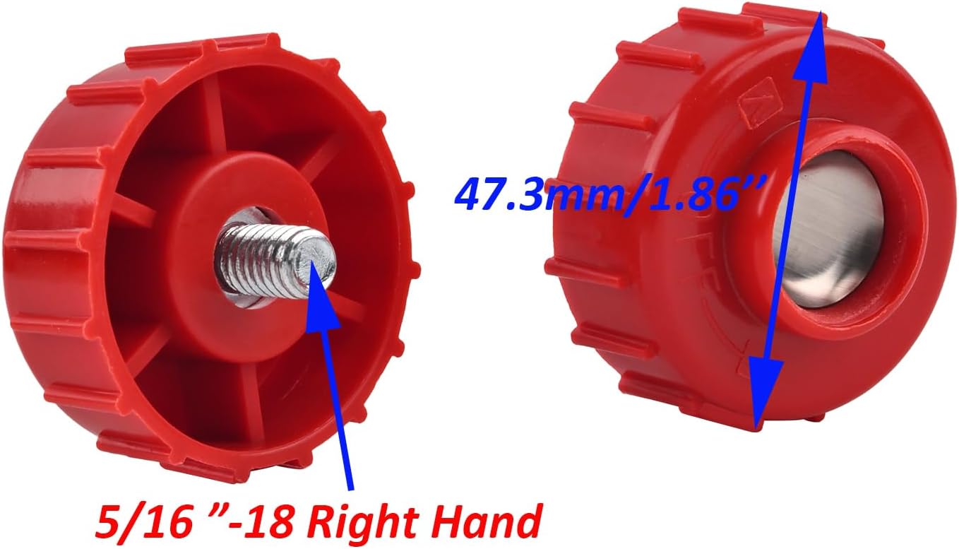
Figure 2: 5/16"-18 Right-Hand Thread Bump Knob (Red)

Figure 3: 5/16"-18 Left-Hand Thread Bump Knob (Black)
- Assemble Trimmer Head:
- Insert the spring into the designated slot within the trimmer head.
- Place the selected bump knob onto the spring, ensuring it sits correctly.
- If your trimmer requires an adapter nut, install it onto the shaft first. The kit includes one adapter nut (green).

Figure 4: Adapter Nut (Green)
- Attach Trimmer Head to Shaft: Align the trimmer head with the shaft of your trimmer. Thread the trimmer head onto the shaft, turning in the appropriate direction (clockwise for right-hand thread, counter-clockwise for left-hand thread) until it is securely fastened. Do not overtighten.
- Load Trimmer Line: Refer to your trimmer's original manual for specific instructions on loading trimmer line into the new head. This head is designed for easy line loading.

Figure 5: Trimmer Head Spool with Line
Operating Instructions (General)
Once the new trimmer head is securely installed and line is loaded, your trimmer is ready for use. Operate your trimmer according to the safety and operating instructions provided in your original trimmer's user manual. This replacement head functions identically to the original, allowing for bump-feed line advancement.
Maintenance
Regular maintenance will extend the life of your trimmer head:
- Clean Regularly: After each use, remove grass clippings, dirt, and debris from the trimmer head. This prevents buildup that can impede line feeding and cause premature wear.
- Inspect for Damage: Periodically inspect the trimmer head for cracks, excessive wear, or damage. Replace the head if any significant damage is observed.
- Check Line: Ensure the trimmer line is properly wound and not tangled within the spool. Replace worn or brittle line as needed.
- Lubrication: No specific lubrication is required for the trimmer head itself, but ensure the trimmer shaft and gearbox (if applicable) are maintained according to your trimmer's manual.
Troubleshooting
| Problem | Possible Cause | Solution |
|---|---|---|
| Trimmer line not feeding | Line tangled or fused; insufficient line; head clogged with debris; worn bump knob. | Rewind line, add more line, clean head, replace bump knob. |
| Trimmer head loose on shaft | Not tightened sufficiently; incorrect thread direction used. | Ensure correct bump knob is used and tighten securely. |
| Excessive vibration | Improperly installed head; damaged head; unbalanced line. | Reinstall head, inspect for damage, ensure line is evenly wound. |
Specifications
| Attribute | Detail |
|---|---|
| Part Number | 841P035132S |
| Brand | Latuwa |
| Compatible Trimmer Models | Hyper Tough H2500, H2510, H2520 |
| Power Source Compatibility | Gas Powered Trimmers |
| Item Weight | 0.69 Pounds (approx. 11 ounces) |
| Product Dimensions (Trimmer Head Base) | Approx. 3.8"L x 3.8"W (97.5mm x 97.5mm)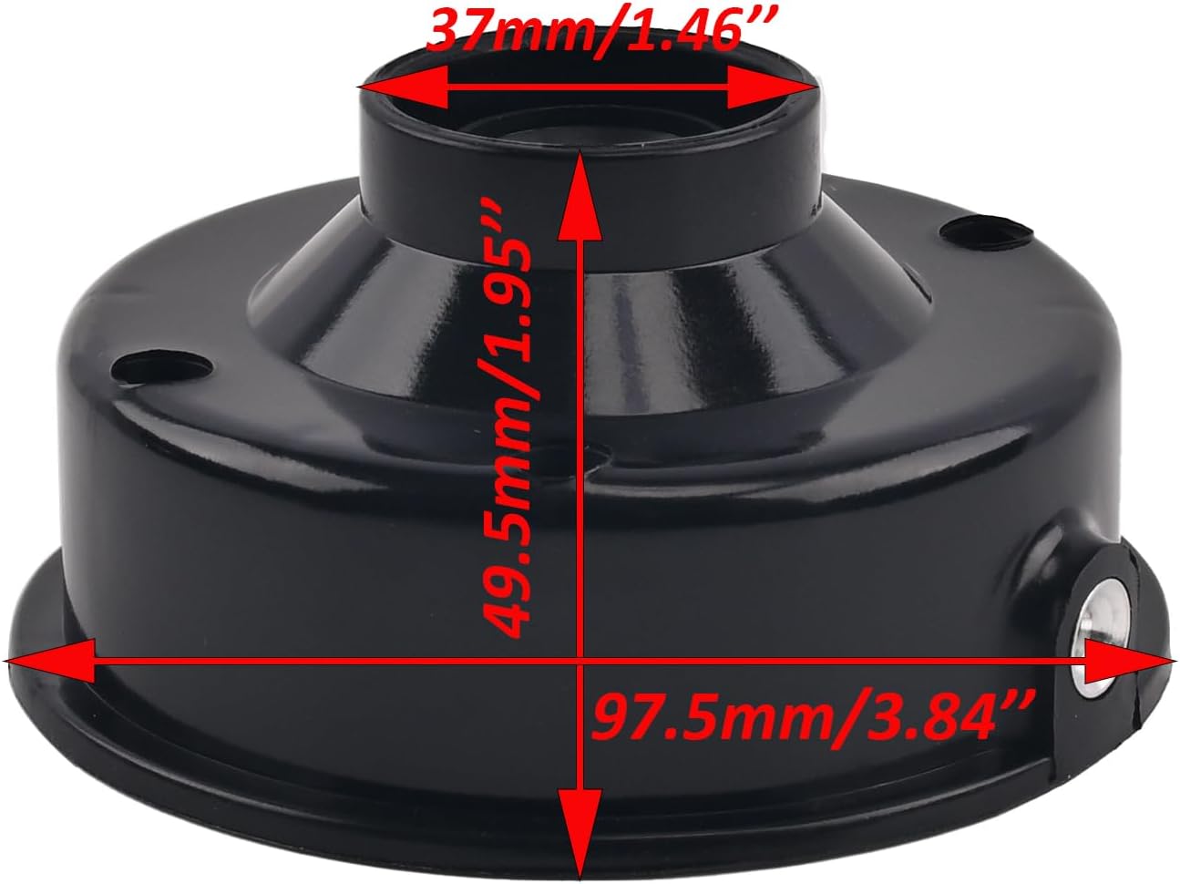 Figure 6: Trimmer Head Base Dimensions |
| Spool Diameter | Approx. 3.03" (77mm) Figure 7: Trimmer Head Spool Diameter |
| Bump Knob Thread Size | 5/16" -18 (Right-Hand and Left-Hand options included) |
Warranty and Support
For information regarding product warranty or technical support, please contact the seller directly through the platform where the purchase was made. Provide your order number and a detailed description of the issue for prompt assistance.
Related Documents - H2510
 |
eyc-tech PHD330 Industrial Differential Pressure Transmitter - Datasheet Technical datasheet for the eyc-tech PHD330 Industrial Differential Pressure Transmitter. Features a piezoresistive sensor, wide measurement range of ±50 to ±10,000 Pa, IP65 aluminum alloy housing, analog output (4-20 mA / 0-10 V), and RS-485 communication. Includes specifications, principle of operation, dimensions, connection diagram, and ordering information. |
 |
Hoover Impulse Cordless Power Mop Owner's Manual This owner's manual provides comprehensive instructions for operating, maintaining, and troubleshooting the Hoover Impulse Cordless Power Mop. It includes safety precautions, assembly details, cleaning procedures for various floor types, and warranty information. |
 |
Hoover Vacuum Cleaner Service Manual and Parts List Comprehensive service manual and parts catalog for Hoover vacuum cleaners, including assembly schematics and detailed part listings for a wide range of models. |