1. Introduction
The Micsig CP503B is a high-frequency AC/DC current probe designed for precise current measurements with oscilloscopes. It offers a bandwidth of DC~50MHz and current ranges of 5A/30A, making it suitable for various electrical testing applications. This manual provides essential information for the proper setup, operation, and maintenance of your CP503B current probe.
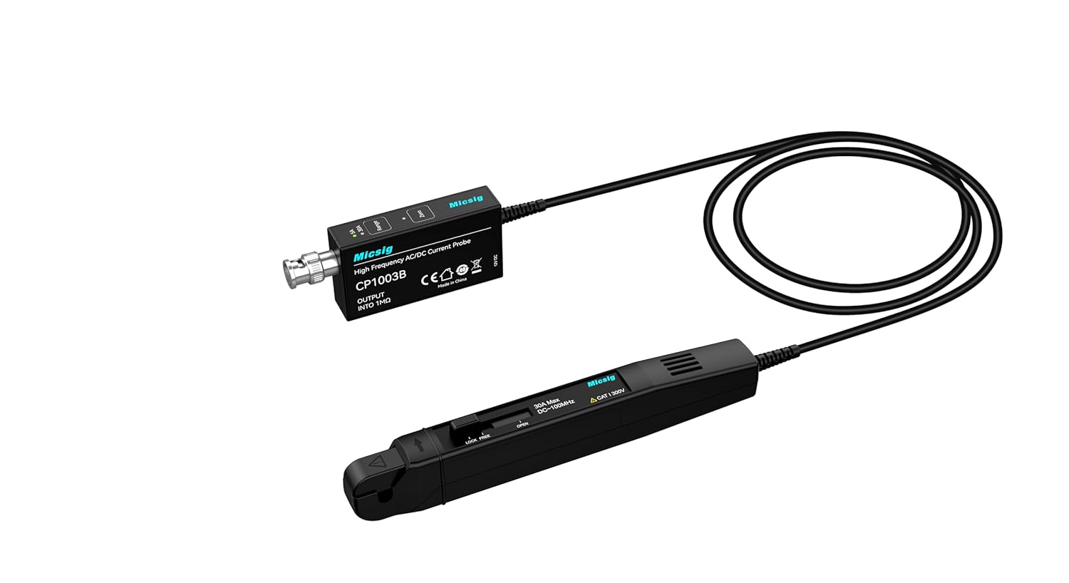
Figure 1: Micsig CP503B High Frequency AC/DC Current Probe.
2. Product Overview and Key Features
The Micsig CP503B current probe is engineered for accuracy and ease of use in demanding measurement environments.
Key Features:
- Bandwidth: DC~50MHz for comprehensive signal analysis.
- Current Range: Selectable 5A/30A for diverse measurement needs.
- DC Accuracy (Typical): ±1% for reliable readings.
- Dual Range Selection: Facilitates accurate measurement of both low and high currents.
- Auto Degaussing and Zero: Simplifies setup and ensures measurement precision.
- Overload Indicator: Provides visual alert for current exceeding the selected range.
- Standard BNC Interface: Ensures compatibility with all standard oscilloscopes.
- Compact and Exquisite Design: Ergonomic for comfortable handling.
Typical Applications:
- Electric vehicle transportation design
- Switching power supply design
- Electronic engineering experiments
- Semiconductor device design
- Avionics design
- Inverter/Transformer design
- Electronic ballast design
- Industrial control and consumer electronics design
- Engine driven design
- Power electronics and electric drive experimental design
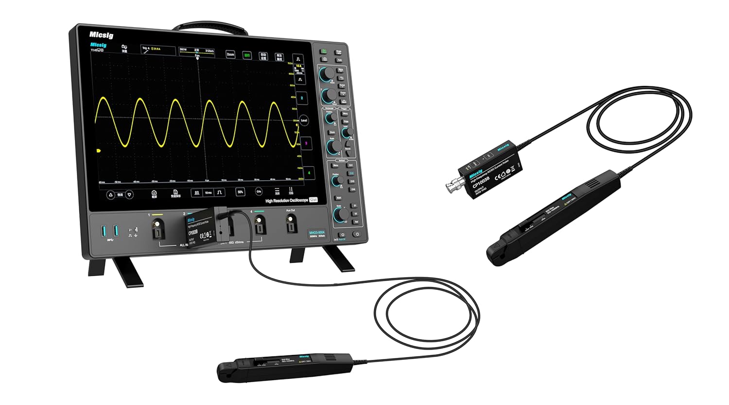
Figure 2: Micsig current probe connected to an oscilloscope.
3. Setup Instructions
Follow these steps to set up your Micsig CP503B current probe for operation.
- Connect to Oscilloscope: Connect the BNC connector of the current probe module to an input channel on your oscilloscope.
- Power Connection: Connect the probe to a DC 5V 3A power source using the provided cable. This typically involves a USB power adapter or a compatible power supply.
- Initial Power On: Once powered, the probe will perform an automatic degaussing and zero adjustment. Allow a few seconds for this process to complete.
- Oscilloscope Settings: Configure your oscilloscope input channel to match the probe's output sensitivity (e.g., 1V/2A or 1V/10A depending on the selected range). Refer to your oscilloscope's manual for specific input scaling settings.

Figure 3: Detailed view of the current probe head.
4. Operating Instructions
Proper operation ensures accurate and safe current measurements.
4.1. Range Selection
The CP503B offers two current ranges: 5A and 30A. Select the appropriate range based on the expected current magnitude of your measurement.
- Press the Range button on the probe module to toggle between 5A and 30A.
- An indicator LED will illuminate next to the selected range (5A or 30A).

Figure 4: Range selection buttons and indicator LEDs.
4.2. Degaussing and Auto Zero Setting
To ensure measurement accuracy, especially for DC current measurements, perform a degaussing and zero adjustment before each measurement or if the probe has been exposed to strong magnetic fields.
- Ensure no current is flowing through the probe jaws.
- Press and hold the Zero button on the probe module until the indicator light flashes. This initiates the degaussing and auto-zero process.
- Release the button. The probe is now zeroed and ready for measurement.

Figure 5: Zero button for degaussing and auto-zero.
4.3. Making a Measurement
To measure current, open the probe jaws and clamp them around the conductor carrying the current you wish to measure. Ensure the jaws are fully closed around a single conductor. The current waveform will be displayed on the connected oscilloscope.
4.4. Overload Indication
If the measured current exceeds the selected range, the overload indicator LED on the probe module will flash. In such cases, switch to a higher current range (e.g., from 5A to 30A) or ensure the current does not exceed the probe's maximum input rating.
5. Application Performance Examples
The CP503B is capable of capturing various current signals with high fidelity.

Figure 6: High-frequency AC current signal (30A, 0.1V/A).

Figure 7: Surge current waveform during power adapter startup (6A, 0.5V/A).
6. Maintenance
To ensure the longevity and accuracy of your Micsig CP503B current probe, follow these maintenance guidelines:
- Cleaning: Use a soft, dry cloth to clean the probe's exterior. Do not use abrasive cleaners or solvents. Ensure no liquids enter the probe housing or BNC connector.
- Storage: Store the probe in a clean, dry environment, away from extreme temperatures, humidity, and strong magnetic fields. The original carrying case is recommended for protection during transport and storage.
- Cable Care: Avoid sharp bends or kinks in the cable. Do not pull the cable to disconnect the probe; always grasp the connector.
- Jaw Integrity: Periodically inspect the probe jaws for any signs of damage or misalignment. Ensure they close completely and smoothly.
7. Troubleshooting
This section addresses common issues you might encounter with your CP503B current probe.
- No Output Signal:
- Ensure the probe is properly powered (DC 5V 3A). Check power indicator lights.
- Verify the BNC connection to the oscilloscope is secure.
- Confirm the oscilloscope input channel is enabled and correctly configured (e.g., input impedance, vertical scale).
- Ensure the probe jaws are fully closed around the conductor.
- Inaccurate Readings / DC Offset:
- Perform a degaussing and auto-zero procedure (refer to Section 4.2).
- Check if the selected current range is appropriate for the measured current.
- Ensure the oscilloscope's vertical scale (V/div) is correctly set according to the probe's output sensitivity (e.g., 1V/2A or 1V/10A).
- Overload Indicator Flashing:
- The measured current exceeds the selected range. Switch to a higher current range (e.g., from 5A to 30A).
- If the indicator still flashes on the highest range, the current exceeds the probe's maximum rating. Do not attempt to measure currents beyond the probe's specifications to avoid damage.
- Probe Runs Warm:
- It is normal for active current probes to generate some heat during operation. If the probe becomes excessively hot or emits smoke/unusual odors, disconnect power immediately and cease use.
8. Specifications
The following table details the technical specifications for the Micsig CP503B and CP1003B current probes.
| Parameter | CP503B | CP1003B |
|---|---|---|
| Model | CP503B | CP1003B |
| Bandwidth | 50MHz | 100MHz |
| Rise Time | ≤7ns | ≤3.5ns |
| Range | 6A (2X) / 30A (10X) | |
| Output Sensitivity | 1V/2A (6A) 1V/10A (30A) | |
| DC Accuracy (typical) | ±1%±10mA (6A) ±1%±50mA (30A) | |
| Delay | <30ns (6A) <30ns (30A) | |
| Current Range | 20mA~6Apk (6A) 50mA~30Apk (30A) | |
| Max. Current Input | 30Apk, 60Apk-pk, 21.21Arms | |
| Noise | ≤ 1.4 mArms (Bandwidth at 20 MHz, Range 30A, 10X) | |
| Max. Working Voltage | CAT I 300V | |
| Max. Floating Voltage | CAT I 300V | |
| Max. Conductor Diameter | 5mm | |
| Overload Indicator | Flashing light | |
| Power Supply | DC 5V 3A | |

Figure 8: Technical specifications and characteristic curves.
9. Warranty Information
Micsig products are typically covered by a limited warranty against defects in materials and workmanship. The specific terms and duration of the warranty may vary by region and product. Please refer to the warranty card included with your product or visit the official Micsig website for detailed warranty information.
10. Support Information
For technical assistance, product inquiries, or service requests, please contact Micsig customer support through the following channels:
- Official Website: Visit the Micsig official website for FAQs, software downloads, and contact forms.
- Email Support: Refer to your product packaging or the Micsig website for the appropriate support email address.
- Authorized Distributors: Contact your local Micsig distributor for regional support.


